User Manual D841 Series
User Manual D841 Series #LX400111; r. 1.
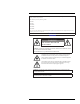
Thank you for purchasing this product. Lorex Corporation is committed to providing our customers with a high quality, reliable security solution. This manual refers to the following models: D841A82 D841A62 D841A81B D841A82B D841A62B For the latest online manual, downloads and product updates, and to learn about our complete line of accessory products, please visit our website at: lorex.com WARNING RISK OF ELECTRIC SHOCK DO NOT OPEN WARNING: TO REDUCE THE RISK OF ELECTRIC SHOCK DO NOT REMOVE COVER.
Table of contents 1 Important Safeguards ............................................................................. 1 1.1 General Precautions....................................................................... 1 1.2 Installation ................................................................................. 1 1.3 Service ...................................................................................... 3 1.4 Use ..................................................................................
Table of contents 11 Motion Detection ..................................................................................34 11.1 Configuring Motion Detection .........................................................34 11.2 Search for Person/Vehicle Detection Events .........................................39 12 Active Deterrence..................................................................................40 12.1 Automatic Deterrence Settings .........................................................
Table of contents 14.8 14.9 14.10 14.11 14.7.8 Upgrading Firmware Manually..............................................69 14.7.9 Automatic Firmware Upgrades ..............................................70 Storage.....................................................................................70 14.8.1 Configuring Hard Drive Overwrite .........................................70 14.8.2 Configuring Recording File Length.........................................71 14.8.3 Configuring Pre-Recording .....
Table of contents 22.6 22.7 22.8 22.9 22.10 23 Storage................................................................................... 102 Special Features ........................................................................ 102 Smart Home............................................................................. 103 Connectivity ............................................................................ 103 Additional Specifications .............................................................
1 Important Safeguards In addition to the careful attention devoted to quality standards in the manufacturing process of your product, safety is a major factor in the design of every instrument. However, safety is your responsibility too. This sheet lists important information that will help to ensure your enjoyment and proper use of the product and accessory equipment. Please read them carefully before operating and using your product. 1.1 General Precautions 1.
1 Important Safeguards 5. Power Sources: This product should be operated only from the type of power source indicated on the marking label. If you are not sure of the type of power supplied to your location, consult your video dealer or local power company. For products intended to operate from battery power, or other sources, refer to the operating instructions. 6. Overloading: Do not overload wall outlets or extension cords as this can result in the risk of fire or electric shock.
1 Important Safeguards 1.3 Service 1. Servicing: Do not attempt to service this product yourself, as opening or removing covers may expose you to dangerous voltage or other hazards. Refer all servicing to qualified service personnel. 2. Conditions Requiring Service: Unplug this product from the wall outlet and refer servicing to qualified service personnel under the following conditions: • • • • • When the power supply cord or plug is damaged.
2 Package Contents Your security recorder package includes the following components: 4K Ultra HD Security DVR Power Adapter Ethernet Cable USB Mouse HDMI Cable NOTE Hard drive size, number of channels, and camera configuration may vary by model. Please refer to your package for specific details. Check your package to confirm that you have received the complete system, including all components shown above. #LX400111; r. 1.
3 Recorder Overview 3.1 Front Panel 1. LED Indicators: • • • HDD: Glows to indicate hard drive is in normal state. Turns off when there is a hard drive error. POWER: Glows to indicate the system is on. NETWORK: Glows when network is in normal state. Turns off when there is a network error. 2. Info / Panic Button: • From live view, press once to open the System Information screen. • Press and hold for 3 seconds to activate the warning lights and sirens on all connected deterrence cameras. 3.
3 Recorder Overview 6. USB Port: Connect a USB mouse (included) to control the system, or a USB flash drive (not included) for data backup or manual firmware updates. 7. DC 12V: Connect the included power adapter. 8. ON/OFF Switch: Turns the DVR on/off. 9. VGA: Connect a VGA monitor (not included) to view the system interface. #LX400111; r. 1.
4 Basic System Setup 4.1 STEP 1: Connect cameras Test your cameras prior to selecting a permanent mounting location by connecting the cameras and cables to your recorder locally. Push and twist the BNC connector clockwise to secure it to the BNC port. NOTE This step is for verification of the camera image only. It is recommended to connect cameras to a nearby power adapter for this step.
4 Basic System Setup 4.4 STEP 4: Connect monitor Connect the recorder to a monitor using the included HDMI cable (supports up to 4K resolution). OR Connect the recorder to a monitor using a VGA cable (not included - supports up to 1080p resolution). CAUTION The system will automatically match the resolution of the connected monitor the first time you use the recorder. If you need to switch monitors, make sure you set the recorder to an output resolution supported by the new monitor BEFORE switching.
4 Basic System Setup 4.6 STEP 6: Lorex Setup Wizard When you first power up your recorder, the Lorex Setup Wizard will begin. The Wizard will help you configure core system settings and set up your cameras. It is recommended to review 5 Camera Installation, page 11 before choosing a permanent mounting position for your cameras. NOTE For detailed mounting instructions for your particular camera model, refer to your camera’s documentation on lorex.com.
4 Basic System Setup 4.8 Quick Access to System Information Perform one of the following actions to bring up the system information window. This window contains vital system information including the model number, serial number, and device ID. NOTE The QR code shown on this screen can be scanned during mobile setup to enter the system’s device ID. To quickly open a window that displays important system information: • From the Live View display, right-click to open the Quick Menu, then click Info.
5 Camera Installation The following chapter provides general setup instruction and installation tips for security cameras. Ensure that you review 5.2 Ensuring Accurate Person/Vehicle Detection, page 11 for channels you are planning to use Person/Vehicle detection on. NOTE Cameras differ in terms of mounting instructions. Please see your camera’s documentation at lorex.com for specific installation instructions. 5.1 Installation Tips General camera installation tips that apply to all camera models.
5 Camera Installation • Install the camera between 8-16ft (2.5-5m) off of the ground. NOTE Accuracy of Person/Vehicle detection will be influenced by multiple factors, such as the object’s distance from the camera, the size of the object, and the height and angle of the camera. Night vision will also impact the accuracy of detection. 5.3 Installing Cameras 1. Mount the cameras to the desired mounting surface according to the instructions that came with the cameras (visit lorex.
5 Camera Installation 5.4 Connecting Camera Extension Cables The extension cable must be a single stretch of cable between the recorder and camera. You cannot connect multiple extension cables to each other. For all extension cable options, including maximum extension cable length, refer to your camera’s documentation at lorex.com. 1. Connect the male power connector on the BNC extension cable to the female power connector on the camera. Connect the BNC connector to the camera. 2.
6 Using the Mouse The mouse is the primary control device for the system. Connect the included mouse to the USB port on the front or rear panel. 1. Left-button: • In live view, while in a split-screen display mode, click an individual channel to view it in full-screen. Click again to return to the split-screen display mode. • While navigating menus, click to open a menu option. 2. Right-button: • During live view, right-click anywhere on the screen to open the Quick Menu.
7 Using the On–Screen Display Use the system’s on–screen display to navigate menus and configure options and settings. NOTE To access the on-screen display, you must connect the included mouse and a monitor (not included) to the recorder. See 4 Basic System Setup, page 7 for full instructions. 7.1 Navigation Bar The Navigation Bar along the bottom of the recorder’s Live View display allows you to access the Main Menu and control basic functions of the recorder.
7 Using the On–Screen Display • Right-click anywhere on the Live View screen. 1. Main Menu: See 14 Using the Main Menu, page 48 for full instructions on using the Main Menu. 2. Playback: Opens the Playback Menu. This allows you to search for video recordings saved on the recorder’s hard drive. For details on using the Playback menu, see 9 Playback, page 23. 3. Pan/Tilt/Zoom: Control and configure settings for Pan-Tilt-Zoom (PTZ) cameras.
7 Using the On–Screen Display 1. Instant Playback: Plays back recent video from the selected channel. By default, instant playback is set to play the last 5 minutes of recorded video. See 14.7.1 Configuring General System Settings, page 64 to set a custom playback length. 2. Digital Zoom: Click to enable digital zoom. Click-and-drag over the camera image to zoom in on the selected area. Right-click to return to the full camera image.
8 Recording By default, the system is set to immediately record video from connected cameras continuously, 24 hours a day. You can customize the recording settings according to your needs. 8.1 Video Recording Types The system supports the following recording types: • Continuous recording: Normal, continuous recording. A icon is shown in the bottom left-hand corner of the camera image when continuous recording is in progress. • Motion recording: Motion-triggered video recording.
8 Recording 4. Configure the following settings. Except where noted, options for Main Stream and Sub Stream are the same: • Super Codec: (Main Stream only) Click to enable ( ) / disable ( ) Super Codec. This setting will help reduce system requirements for unimportant recordings to maximize hard drive storage. • Video: (Sub Stream only) Click to enable ( ) / disable ( ) Substream video. CAUTION Disabling Substream video will prevent you from viewing the system remotely over the Internet.
8 Recording 2. Click STORAGE. Click the SCHEDULE tab on the side panel, then Record on the top panel. 3. Under Channel, select the channel you would like to configure or select All. 4. Configure the schedule as needed: • Check Continuous, MD (Motion Detection), or Alarm to select the recording type you would like to configure. • Click-and-drag on each day to customize the recording schedule. The schedule is set up as a grid, which each block representing one hour.
8 Recording To set options for manual recording: 1. From the Live View display, right-click to open the Quick Menu, then click Manual Record. 2. Under Main Stream, select how the system will record the Main Stream for each channel: • Auto: Main Stream recording will follow the recording schedule. • Manual: The system will record the Main Stream continuously as long as this option is checked. • Stop: The system will not record the Main Stream for this channel. This option is not recommended. 3.
8 Recording 4. Click Apply. #LX400111; r. 1.
9 Playback Search through and playback recorded video files on the system. 9.1 Playing Back Video from the Hard Drive To play back recorded video: 1. From the Live View display, right-click to open the Quick Menu, then click Playback. 2. Use the calendar on the right to select the day to playback. 3. Check the channels you want to play back. Click the icons to the right of each channel name to choose the video quality ( for Main Stream, for Sub Stream). 4.
9 Playback 4. Viewing Modes: • Bookmark List: Shows all bookmarked recordings for a single channel on the selected date. • File List: Shows all available recordings for the selected date and channel(s) in list format. • Fullscreen: Shows video in fullscreen. Right-click to return to split-screen viewing. 5. Zoom Playback Bar: Select the scope of the playback bar. 6. Recording Type Filters: Click to show/hide recording types. 7. Playback Bar: Click inside the bar to select a playback time.
9 Playback 8. Playback Controls: • / • Stop • Play Backwards • Previous Frame: Go to the previous frame when video is paused. • Next Frame: Go to the next frame when video is paused. Play / Pause • Slow Playback: Click repeatedly to slow the video down by half speed up to 16× slower than normal. Click again to return to regular speed. • Fast Playback: Click repeatedly to double the speed of the video up to 16× faster than normal. Click again to return to regular speed.
9 Playback 9.3 Playing Back Video from a USB Drive If you have video files saved to a USB flash drive (not included), you can play them back using the system. For full instructions on backing up video to a USB flash drive, see 10 Backup, page 29. To play back video from a USB flash drive: 1. Connect the USB thumb drive (not included) with video files on it into a free USB port on the recorder. 2. From the Live View display, right-click to open the Quick Menu, then click Playback. 3.
9 Playback To perform a Smart Search: 1. From the Live View display, right-click to open the Quick Menu, then click Playback. 2. Use the calendar on the right to select the day to playback. 3. Check a single channel you want to play back. Click the icon to the right of the channel name to choose the video quality ( for Main Stream, for Sub Stream). 4. Click inside the video bar to select the playback time. The system will begin playing back video from the selected time. 5.
9 Playback 3. Use the calendar on the right to select the day to playback. 4. Check the channels you want to play back. Click the icons to the right of each channel name to choose the video quality ( for Main Stream, for Sub Stream). 5. Click inside the video bar to select the playback time. The system will begin playing back video from the selected time. 6. Click eo clip. to mark the beginning of the video clip, then click again to mark the end of the vid- 7. Click to open the backup menu. 8.
10 Backup Backup video files to external USB flash drive (not included). 10.1 Formatting the USB Flash Drive It is recommended to format your USB thumb drive (not included) before using it with the system. CAUTION Formatting the USB device will permanently erase all data. This step cannot be undone. Prerequisite: • Connect a USB flash drive (not included) to a free USB port on the unit. To format a USB flash drive: 1. From the Live View display, right-click to open the Quick Menu, then click Main Menu.
10 Backup 2. Click BACKUP. 3. Configure the following: • Device Name: Select the USB device you would like to back up files to. • Path: Click Browse to locate a folder path on the USB drive to save your files to. • Record CH: Select the channel you would like to search or select All to search all channels. • Type: Select the recording type you would like to search for or select All to search all recording types. • Start Time / End Time: Select the start and end time for your search.
10 Backup 2. Double-click one of the files on the left to begin playback. OR Click to open a back up video file in another location 3. Use the Lorex Player controls to control playback or select other files for playback. NOTE For a full overview of Lorex Player controls, see 10.4.3 Lorex Player Controls, page 32. 10.4.2 Viewing Backed Up Files on Mac 1. Download and install the Lorex Player for Mac from the recorder’s product page at lorex.com 2.
10 Backup 5. Use the Lorex Player controls to control playback or select other files for playback. NOTE For a full overview of Lorex Player controls, see 10.4.3 Lorex Player Controls, page 32. 10.4.3 Lorex Player Controls 1. File List: Double-click to open a file. 2. Viewing Mode: Select between single-channel viewing and various split-screen options. 3. Hide/Show File List 4. Playback Controls: • : Playback files in sequence. • : Synchronize playback times. • : Play/pause playback.
10 Backup 6. Display Area: Double-click a video file to expand. Click the controls inside the display area to do the following: • : View information about the video file. • : Start/stop a manual recording from the video file. • : Take a snapshot from the video file. • : Close the video file. 7. Add Files: Click to open backed up video files. 8. Export Files: Export a video file to a different format. 9. Digital Zoom: Click, then click-and-drag over a camera image to zoom in.
11 Motion Detection In addition to general motion detection, the system supports smart Person/Vehicle detection. Both types of detection can be configured using the menu shown below. 11.1 Configuring Motion Detection Set preferences for motion detection on each channel, and select channels you want to enable smart Person/Vehicle detection on. CAUTION A maximum of 4 channels will support Person/Vehicle detection at once. By default, channels 1-4 have Person/Vehicle detection enabled.
11 Motion Detection 5. Click Setup next to Area to configure which areas of the image will be enabled for motion detection. A grid will appear on the monitor: • The camera image appears with a red grid overlay. This means the entire image is enabled for motion detection. • Click or click-and-drag to add / remove boxes from the active area. Cells that have been removed from the active area appear green. • Hover near the top of the image to reveal zone selection.
11 Motion Detection 7. Choose how the system will react when motion is detected: • Show Message: Check to enable an on-screen pop-up when one of your cameras detects motion. On-screen pop-up shows the channels an event occurred on and the type of event. • Send Email: Check to enable email alerts. You must configure email alerts before you will be able to receive them (see 14.6.3 Configuring Email Alerts, page 61).
11 Motion Detection 8. Click Smart Motion Detection to enable Person/Vehicle detection: NOTE See 5.2 Ensuring Accurate Person/Vehicle Detection, page 11 for important camera installation notes related to channels with Person/Vehicle detection enabled. #LX400111; r. 1.
11 Motion Detection #LX400111; r. 1.
11 Motion Detection • Click Enable to activate Person/Vehicle detection on the selected channel. CAUTION A maximum of 4 channels will support Person/Vehicle detection at once. By default, channels 1-4 have Person/Vehicle detection enabled. • Select a Sensitivity level (a high sensitivity value will detect smaller objects than a low value). • Check Person/Vehicle. • Click OK when finished. 9. Click Apply. 10.
12 Active Deterrence Lorex Active Deterrence cameras feature a bright customizable warning light and a remote-triggered siren. The recorder allows you to customize automatic light-triggering when motion is detected to deter intruders (see 12.1 Automatic Deterrence Settings, page 40). You can also trigger the lights and sirens manually using the recorder or Lorex connectivity software (see 12.2 Manually Activate Deterrence Features, page 42).
12 Active Deterrence 5. Click Setup next to Warning Light to configure preferences: • Duration: Choose how long the warning light will stay on when motion is detected. • Select Warning Light for a solid white light, or Strobe for a flashing light. If you select Strobe, set how quickly the light will flash under Strobe Frequency. 6. Click Setup next to Area to set an active area for automatic deterrence. • The camera image appears with a grid overlay. The green area is the active area for deterrence.
12 Active Deterrence 7. Click Setup next to Schedule to set the weekly schedule for automatic deterrence. • The default schedule is active during the night, between 5pm and 7am. • Click Modify to change the schedule for the corresponding day of the week. • Click OK when finished. 12.2 Manually Activate Deterrence Features The system has multiple options for activating deterrence features.
13 Managing Passwords and User Accounts Passwords are enabled by default and are required to access the Main Menu or connect to the system using a computer or mobile device. You will be prompted to create a custom password after you connect for the first time. NOTE If you forget the password to the system, contact technical support to have it reset. 13.
13 Managing Passwords and User Accounts 13.1.2 Adding Users You can allow multiple users to log in to the system. When adding different users, you can assign what menus they have access to. For example, you may want your friend to monitor your system while you are away, while not giving full access to your system. To add a user: 1. From the Live View display, right-click to open the Quick Menu, then click Main Menu. 2. Click ACCOUNT, then click the USER tab. 3. Click Add User. #LX400111; r. 1.
13 Managing Passwords and User Accounts 4. Configure the following: • User Name: Enter a name for the user account. • Password: Enter a password for the user account. Enter the password again under Confirm Password. • Memo: (Optional) Enter a description of the user account. • Group: Select the group you would like to assign to this user account. A user account cannot be given permissions its group does not have.
13 Managing Passwords and User Accounts To add a group: 1. From the Live View display, right-click to open the Quick Menu, then click Main Menu. 2. Click ACCOUNT, then click the GROUP tab. 3. Click Add Group. 4. Configure the following: • Group Name: Enter a name for the group. • Memo: (Optional) Enter a description of the group. • Authority: Check the permissions you would like the user account to have. Under the System tab, select the menus the user account may access.
13 Managing Passwords and User Accounts 4. Update group details as needed, then click OK. 13.2.3 Deleting Groups Remove a group. To delete a group: 1. From the Live View display, right-click to open the Quick Menu, then click Main Menu. 2. Click ACCOUNT, then click the GROUP tab. 3. Click next to the group you want to delete. 4. Click OK. #LX400111; r. 1.
14 Using the Main Menu To access the main menu: • From the Live View display, right-click to open the Quick Menu, then click Main Menu. OR • Click 14.1 on the Navigation Bar, then click Main Menu. Playback See chapter 9 Playback, page 23 for details. 14.2 Alarm Set preferences for alarm events such as video loss, motion detection, Person/Vehicle detection, and system warnings. The Alarm menu is also used to set preferences for deterrence cameras. 14.2.
14 Using the Main Menu 4. Enter a start and end time for your search. 5. Click Search. 6. Alarm events that match your search criteria are displayed: • The Event column is formatted to show <[Event Type]: [Channel Number]>. • Click Details to see more information on the selected event. • Motion events have more options than other alarm events. You can view the event by clicking in the Playback column, or back up the video clip to a USB flash drive (not included) by clicking Backup. 14.2.
14 Using the Main Menu 5. Click to set a weekly schedule for video loss events. By default, video loss events are enabled at all times. • Click or click-and-drag along the each of the yellow timelines to quickly add or remove time from each day’s schedule in 15–minute segments. • Click beside 2 or more days to link schedules ( change multiple schedules at once. ). This allows you to quickly • To make fine adjustments to a schedule, click Modify.
14 Using the Main Menu 2. Click ALARM. Click the WARNING tab on the side panel, then HardDisk on the top panel. 3. Choose the event type you want to set preferences for: • No Disk: No hard drive detected. • Disk Error: A hard drive error has been detected. • Disk Full: The hard drive is full or almost full. Enter the percentage of disk space remaining that will trigger a warning next to Less Than. Disk Full warnings will not occur if hard drive overwrite is enabled.
14 Using the Main Menu 5. Choose how the system will react when the selected event occurs: • Show Message: Error message will appear on the recorder’s display. • Record Channel: For Net Disconnection events only. Select the numbered tiles next to this option to record video from the corresponding channels. Set the length of recording following a network disconnection event in the Post_REC field. • Buzzer: The recorder will sound an audible alarm.
14 Using the Main Menu NOTE Audio will only be heard if you are viewing an audio-enabled camera in single-channel view. You will also need an HDMI monitor with built-in speakers, or an external speaker connected to the recorder’s Audio Out port (see 18 Connecting Audio Devices, page 87 for details). To set preferences for listen-in audio: 1. From the Live View display, right-click to open the Quick Menu, then click Main Menu. 2. Click DISPLAY, then click the DISPLAY tab. 3. Check Live Audio. 4.
14 Using the Main Menu 4. Click Apply. 14.4.4 General Display Settings Configure miscellaneous display settings. To configure general display settings: 1. From the Live View display, right-click to open the Quick Menu, then click Main Menu. 2. Click DISPLAY, then click the DISPLAY tab. 3. Check to display system time during Live View. NOTE Disabling time display will not affect timestamps in recorded video. 4. Check to display channel names during Live View. 5.
14 Using the Main Menu 2. Click DISPLAY, then click the VIEW tab. 3. Select the viewing mode you would like to configure ( ). Use the numbered dropdown menus in each viewing window to choose the channel that will appear in each window. 4. Click Apply. NOTE You can also click-and-drag channels during Live View to change the display order. 14.4.6 Configuring Sequence Mode Sequence mode cycles through connected channels to give you an overview of what is happening on all cameras.
14 Using the Main Menu 2. Click DISPLAY, then click the SEQUENCE tab. 3. Click to enable ( ) / disable ( ) Sequence mode. NOTE • Enabling Sequence mode is not necessary for configuration. • You can also enable Sequence mode from Live View by clicking clicking to open the Quick Menu and clicking Sequence. on the Navigation Bar, or by right- 4. Enter the time in seconds to remain on each channel or split screen during Sequence mode. 5.
14 Using the Main Menu 2. Click CAMERA, then click the IMAGE SETTINGS tab. 3. 4. 5. 6. Select the channel you want to configure. Select COAXIAL for cameras connected using BNC cabling, or UTP for balun installations. Configure the color settings for the selected channel. Click Apply. 14.5.2 Configuring Snapshot Recording The system can be set to record snapshot images when a camera detects motion.
14 Using the Main Menu 5. Click Apply. 6. (OPTIONAL) Click Copy to apply the settings for the current channel to one or more other channels (see 14.11 Copying Settings to Another Channel, page 79 for full instructions on using the copy function). 14.5.3 Changing On-Screen Overlay Remove or change the location of the date/timestamps and channel names. You can also change channel names from this menu. To change the on-screen overlay: 1.
14 Using the Main Menu 2. Click CAMERA. Click the OVERLAY tab on the side panel, then Privacy Masking on the top panel. 3. Select the channel you want to configure. 4. Configure the following settings: • Preview: Check to set and preview privacy masks. • 1–4: Click the numbered boxes to create a corresponding privacy mask on the camera image. • Record: Check to include privacy masks in video recordings. Leave unchecked if you would like privacy masks only to show during Live View. 5.
14 Using the Main Menu 14.5.6 Camera Firmware Upgrade (CVI Upgrade) Manually upgrade camera firmware. This is typically only necessary if directed to do so by Lorex technical support. Prerequisite: • Connect a USB flash drive (not inlcuded) to the recorder with the .bin camera firmware file(s) preloaded. To manually upgrade camera firmware: 1. From the Live View display, right-click to open the Quick Menu, then click Main Menu. 2. Click CAMERA, then click the CVI UPGRADE tab. 3.
14 Using the Main Menu 3. Configure the following settings: • IP Version: Select IPv4 or IPv6. • DHCP: Click to enable ( ) / disable ( ) DHCP. It is recommended to enable DHCP to let the system automatically obtain an IP address from the router. If you are an advanced user, disable DHCP to assign a static IP address to the system. To assign a static IP address, configure the following: ◦ IP Address: Enter the IP address you would like to assign to the system.
14 Using the Main Menu 2. Click NETWORK, then click the EMAIL tab. 3. Click to enable ( ) email alerts. #LX400111; r. 1.
14 Using the Main Menu 4. Configure the following: If you want to use Lorex’s email server (recommended): • Mail Select: Select Lorex Mail. • Receiver: Select up to 3 email addresses that will receive alerts. Enter each email address into the field Email Address below. • Subject: Enter a subject line for email alerts. • Attachment: Enable ( ) to include a image attachment of the camera. NOTE You must enable the Snapshot option for motion detection on each camera you would to receive attachments.
14 Using the Main Menu CAUTION P2P connection is the primary method used for remote access to your security system using the Lorex Home app. If you disable P2P connectivity, you will only be able to access your system over the Internet using DDNS. See 20 DDNS Setup (Advanced), page 96 for details. To change P2P setting: 1. From the Live View display, right-click to open the Quick Menu, then click Main Menu. 2. Click NETWORK, then click the P2P SETTING tab. 3.
14 Using the Main Menu 3. Configure the following: • • • • • Device Type: Shows the model number of your system. Device No.: Select the remote control address of the system. Language: Set the system languages. Available options are English, French, and Spanish. Video Standard: Select NTSC (North America) or PAL (Europe). Instant Playback: Select the amount of time (in minutes) the system will go back when instant playback is activated in live view.
14 Using the Main Menu 4. Configure Daylight Savings Time (DST) settings: • DST: Click to enable ( ) / disable ( ) Daylight Savings Time. • DST Type: Select Week to set the start and end time based on a day and week (e.g., 2nd Sunday of March), or select Date to set the start and end time to a specific date. • Start Time / End Time: Set start and end times for DST. Format will change depending on your selection for DST Type. 5.
14 Using the Main Menu 3. Click Add New Holiday. 4. Configure the following: • Holiday Name: Enter a name for this holiday. • Repeat Mode: Select Once for the holiday to occur only this year or Always for the holiday to be repeated each year. • Holiday Range: Select Date to select a specific date, or select Week to select holidays based on which week they fall on. • Start Time / End Time: Set the start and end time for this holiday. • Add More: Click to enable ( ) to configure another holiday. 5.
14 Using the Main Menu 5. Configure the following: • To add a single IP address to the selected filter type, enter it into Start Address, then click Add IP Address. • To add a range of IP addresses to the selected filter type, enter the Start Address and End Address, then click Add IP Section. 6. Click Apply. 14.7.5 Save System Settings to a USB Flash Drive The system allows you to save your current system configuration to a USB flash drive (not included).
14 Using the Main Menu 2. Click SYSTEM, then click the CONFIG BACKUP tab. 3. Under Device Model, select the USB device where a system configuration has been saved. 4. Click the folder with the configuration files you would like to restore. Configuration file folders are labeled Config and then the time and date the configuration was saved (e.g., Config_ 20140425103727). 5. Click Import to save your current system configuration. 14.7.7 Restoring Default Settings Reset the system to default settings.
14 Using the Main Menu To upgrade firmware manually: 1. From the Live View display, right-click to open the Quick Menu, then click Main Menu. 2. Click SYSTEM, then click the UPGRADE tab. 3. Click Browse. 4. Click on the .bin firmware file for your recorder. 5. Click Start. 14.7.9 Automatic Firmware Upgrades Firmware upgrades provide enhanced functionality. The system will automatically check for firmware upgrades if it is connected to the Internet. To configure automatic firmware upgrade: 1.
14 Using the Main Menu 2. Click STORAGE, then click the BASIC tab. 3. Ensure HDD Full is set to Overwrite to overwrite the oldest recordings when the hard drive is full. NOTE Selecting Stop Record for the system to stop recording when the hard drive is full. 4. Click Apply. 14.8.2 Configuring Recording File Length Select how the system will store video files. To configure recording length: 1. From the Live View display, right-click to open the Quick Menu, then click Main Menu. 2.
14 Using the Main Menu 2. Click STORAGE. Click the SCHEDULE tab on the side panel, then Record on the top panel. 3. 4. 5. 6. Under Channel, select the channel you would like to configure or select All. Set the duration for pre-recording in seconds. Click Apply. (OPTIONAL) Click Copy to apply the settings for the current channel to one or more other channels (see 14.11 Copying Settings to Another Channel, page 79 for full instructions on using the copy function). 14.8.
14 Using the Main Menu 4. Configure the schedule as needed: • Check Continuous, MD (Motion Detection), or Alarm to select the recording type you would like to configure. • Click-and-drag on each day to customize the recording schedule. The schedule is set up as a grid, which each block representing one hour. • Click beside 2 or more days to link schedules ( change multiple schedules at once. • To make fine adjustments to a schedule, click and end times for a schedule. ). This allows you to quickly .
14 Using the Main Menu • Read-only HDD: The system can playback data from this hard drive, but it will not record to it. To configure hard drive types: 1. From the Live View display, right-click to open the Quick Menu, then click Main Menu. 2. Click STORAGE, then click the HDD MANAGER tab. 3. Under Type next to the hard drive you want to configure, select Read/Write or Read only. 4. Click Apply. 14.8.
14 Using the Main Menu 4. For Recording Days mode, click Select to choose your hard drive from a list to output the total number of days your hard drive can store. For Disk Requirement mode, enter a number of days to output the total amount of storage required. 14.8.8 FTP (Advanced) Send recordings and/or snapshots to an FTP server. To configure FTP settings: 1. From the Live View display, right-click to open the Quick Menu, then click Main Menu. 2. Click STORAGE, then click the FTP tab. 3.
14 Using the Main Menu 14.10.1 Version Info The Version sub-menu allows you to view information about the current firmware installed on the system. To access the Version menu: 1. From the Live View display, right-click to open the Quick Menu, then click Main Menu. 2. Click INFORMATION, then click the VERSION tab. 14.10.2 Log The Log menu allows you to search for system logs. To search for system logs: 1. 2. 3. 4. 5.
14 Using the Main Menu To access the Event Status menu: 1. From the Live View display, right-click to open the Quick Menu, then click Main Menu. 2. Click INFORMATION, then click the EVENT STATUS tab. The following alarms are shown in the Event Status menu: • • • • • • • • No HDD: No Hard drive is detected. Disk Error: Hard drive error detected. Disk Full: Hard drive is full. Net Disconnection: System is not connected to the network.
14 Using the Main Menu To access the Online Users menu: 1. From the Live View display, right-click to open the Quick Menu, then click Main Menu. 2. Click INFORMATION. Click the NETWORK tab on the side panel, then Online User on the top panel. 14.10.6 Load The Load menu shows you the network traffic your system is sending and receiving. To access the Load menu: 1. From the Live View display, right-click to open the Quick Menu, then click Main Menu. 2. Click INFORMATION.
14 Using the Main Menu 2. Click INFORMATION. Click the NETWORK tab on the side panel, then Network Test on the top panel. 14.10.8 BPS The BPS menu shows the bitrates of connected cameras. The bitrate is the amount of data the camera is sending to the system. To access the BPS menu: 1. From the Live View display, right-click to open the Quick Menu, then click Main Menu. 2. Click INFORMATION, then click the BPS tab. 14.
15 Connecting Remotely using the Lorex Home Mobile App You can connect to your security system over the Internet using our free Lorex Home app for iOS and Android devices. Securely connect to your system from anywhere with no recurring fees for live viewing.
16 Smart Home & Voice Assistance The recorder is compatible with third-party smart home solutions, including Amazon Alexa®, Google Assistant®, IFTTT and Apple TV®. You can use these services to take your security experience to the next level, with smart home options that make accessing your system even easier. For compatibility information, as well as full instructions on setup and use, visit lorex.com/SmartHome. To enable Smart Home services on the recorder: 1.
17 Pan/Tilt/Zoom (PTZ) Cameras Pan/Tilt/Zoom (PTZ) cameras are specialty cameras that move according to commands given by the recorder. You can move PTZ cameras manually using the recorder’s on-screen display, or create preset locations and patterns for the camera to follow automatically. 17.
17 Pan/Tilt/Zoom (PTZ) Cameras STEP 2: Camera configuration 1. From the Live View display, right-click to open the Quick Menu, then click Main Menu. 2. Click CAMERA, then click the IMAGE SETTINGS tab. 3. Select the channel you want to configure. 4. Configure the highlighted fields as needed. NOTE For Lorex HD PTZ cameras, there is no need for configuration — leave all fields at their default values. For third-party PTZ cameras, select Serial next to Control Mode.
17 Pan/Tilt/Zoom (PTZ) Cameras 1. Navigation Controls: Click the directional arrows to move the PTZ camera manually. 2. Zoom-to-Area: Click, then click-and-drag to draw a box on the camera image. The PTZ camera will zoom in to the selected area. 3. Mouse Tracking: Click to enable/disable mouse tracking. When enabled, click-and-drag in the direction you would like the PTZ camera to move. The camera will follow the path of the mouse cursor. 4. PTZ Settings: • Speed: The speed of PTZ camera movement.
17 Pan/Tilt/Zoom (PTZ) Cameras 1. No.: Enter the ID number for a preset, tour, or pattern you want to activate. 2. Preset: Move the camera to the preset number specified in the No. field. For instructions on setting up preset locations, see 17.4 Presets, page 85. 3. AutoPan: Set the camera to rotate 180° back and forth. 4. Tour: Perform the tour number specified in the No. field. For instructions on creating a tour, see 17.5 Tours, page 85. 5. Flip: Rotate the camera 180° from its current position. 6.
17 Pan/Tilt/Zoom (PTZ) Cameras To add patterns: 1. From the Live View display of your PTZ camera, right-click to open the Quick Menu, then click Pan/Tilt/Zoom. 2. The PTZ controls open. Click 3. 4. 5. 6. to open advanced PTZ controls, then click . Click the Pattern tab. Under Pattern, enter the number of the pattern you want to create. Move the camera to the desired starting position, then click Start. Using the on-screen controls, move the camera in any pattern you wish. When finished, click End.
18 Connecting Audio Devices The system supports Lorex HD audio cameras, which transmit audio through the same coax cable used for video connection. The system can also record one audio channel using the AUDIO IN port on the rear panel. You must have a self-powered microphone or an audio camera with an RCA–type audio connection to use this port. NOTE Use of an external microphone allows you to record audio on Channel 1 of the system. It cannot be moved to a different channel.
18 Connecting Audio Devices 4. Click Audio Setting, then configure the following: • Audio Recording: Click to enable ( ) / disable ( ) audio recording. CAUTION Audio recording and / or use of listen-in audio without consent is illegal in certain jurisdictions. Lorex Corporation assumes no liability for use of its products that does not conform with local laws. • Audio Format: Choose the desired format for audio recording (G711a or AAC recommended). • Audio Source: Select HDCVI. • Click OK. 5.
18 Connecting Audio Devices 4. Click Audio Setting, then configure the following: • Audio Recording: Click to enable ( ) / disable ( ) audio recording. CAUTION Audio recording and / or use of listen-in audio without consent is illegal in certain jurisdictions. Lorex Corporation assumes no liability for use of its products that does not conform with local laws. • Audio Format: Choose the desired format for audio recording (G711a or AAC recommended). • Audio Source: Select NORMAL. • Click OK. 5.
19 Replacing the Hard Drive The system comes with a pre-installed 3.5" SATA hard drive. You can replace the hard drive with one up to a maximum size of 10TB. 19.1 Removing the Hard Drive CAUTION Make sure that the system is OFF and the power adapter is disconnected before removing/installing a hard drive. To remove the hard drive: 1. Power off the system, and unplug all cabling from the system. 2. Turn the recorder over. Remove the bottom panel screws (6×). #LX400111; r. 1.
19 Replacing the Hard Drive 3. Turn the recorder over carefully, then remove the top panel. CAUTION The wiring to the front panel button and USB port runs along the top panel of the recorder. When separating the top panel, rest it carefully beside the bottom panel as shown below. #LX400111; r. 1.
19 Replacing the Hard Drive 4. Remove the power and SATA cables from the hard drive. 5. Carefully pick up the hard drive to lift the bottom panel, being mindful of the sharp edges of the bottom panel. Remove the hard drive screws (4×) from the bottom panel. Hold onto the hard drive so it remains in place when all screws have been removed. 6. If you are not immediately going to install a new hard drive, replace the top panel and the 6 bottom panel screws. #LX400111; r. 1.
19 Replacing the Hard Drive 19.2 Installing a New Hard Drive CAUTION Make sure that the system is OFF and the power adapter is disconnected before removing/installing a hard drive. To install a new hard drive: 1. Insert the 2 hard drive screws closest to the SATA and power ports on the hard drive and tighten them half way. 2. Power off the system, and unplug all cabling from the system. 3. Turn the recorder over. Remove the bottom panel screws (6×). #LX400111; r. 1.
19 Replacing the Hard Drive 4. Turn the recorder over carefully, then remove the top panel. CAUTION The wiring to the front panel button and USB port runs along the top panel of the recorder. When separating the top panel, rest it carefully beside the bottom panel as shown below. 5. Line the 2 half-inserted hard drive screws with the 2 holes shown below. #LX400111; r. 1.
19 Replacing the Hard Drive 6. Carefully pick up the bottom panel with the hard drive, being mindful of the sharp edges of the bottom panel. Slide the 2 pre-inserted screws into the locked position, then tighten the screws. Insert and tighten the 2 remaining hard drive screws. 7. Connect the power and SATA cables to the hard drive. 8. Replace the top panel and the 6 bottom panel screws. #LX400111; r. 1.
20 DDNS Setup (Advanced) Setting up DDNS connectivity allows you to view your recorder from any computer or compatible mobile device with Internet access. NOTE The primary connectivity option for the recorder uses the Lorex Home app to connect to your system over the Internet without the need for port forwarding or DDNS registration. • 20.1 For instructions on using the Lorex Home app for mobile devices, see 15 Connecting Remotely using the Lorex Home Mobile App, page 80.
20 DDNS Setup (Advanced) 2. Select Create an Account. NOTE If you have already set up an account, select I Have a LOREX Account and log in. Proceed directly to , page . 3. Enter basic information for account setup. 4. Click Create an Account. 20.3 STEP 3: Activate Your Warranty Activate the manufacturer’s warranty on your recorder. To activate your product warranty: 1. 2. 3. 4. From your Lorex account, click the WARRANTIES tab. Click Activate Warranty.
20 DDNS Setup (Advanced) 1. From your Lorex account, click the DDNS tab. 2. Click Set up a New DDNS. 3. Select your recorder warranty from the dropdown next to Warranty. Enter the rest of your product information. NOTE • The Device Name can be any name of your choice (for example, “Store Security System”). • You can find your recorder’s MAC Address in the system information window on the recorder. From the Live View display, right-click and click Info, or click on the Navigation Bar. 4.
20 DDNS Setup (Advanced) 4. Configure the following: • • • • DDNS Type: Select Lorex DDNS. Domain Name: Enter the first part of the DDNS domain that you requested during setup. User ID: Enter the username provided in the DDNS confirmation email. Password: Enter the password provided in the DDNS confirmation email. 5. Click Apply. You will now be able to access your system remotely using DDNS. Enter the full domain name into a web browser (e.g., http://www.tomsmithsecurity.lorexddns.
21 Troubleshooting When a malfunction occurs, it may not be serious or difficult to correct. The following chart contains solutions to most common problems. Please refer to the topics below before calling Lorex Technical Support. Error Possible Causes Solutions System is not receiving power, or is not powering up. Cable from power adapter is loose or is unplugged. • • Cables are connected, but system is not receiving sufficient power. • • • Confirm that all cables are connected correctly.
21 Troubleshooting Error Possible Causes Solutions Mouse not detected by system. Mouse cable is not firmly connected to the system, or the mouse is not connected to the system. Firmly connect the mouse cable to one of the USB ports. System needs to be reset. Power off the system (disconnect power cable). Firmly connect a USB mouse to one of the USB ports. Reconnect the power cable to the 12V DC port on the rear panel.
22 Technical Specifications 22.1 General Video Transmission Technology Channels 22.2 Inputs/Outputs Video Input(s) Video Outputs(s)1 Audio Input(s) Audio Output(s) 22.3 Display Display Output Resolution Live Display Live Display Speed (Max) OSD System Navigation 22.4 Recording Recording Resolution Recording Frame Rate Recording Schedule Back-up File Format Video Compression 22.5 Playback Simultaneous Playback Playback Speed Search 22.
22 Technical Specifications 22.8 Smart Home Amazon Alexa Google Assistant Streaming Options 22.9 Connectivity Mobile Viewing Compatible App PC/MAC Remote Viewing Email Notification Network Interface DDNS USB Interface 22.10 Additional Specifications FW Upgrade Watchdog Function Power Consumption Supply Voltage Unit Dimensions (W × D × H) Unit Weight Operating Temperature Humidity Disclaimers: 1. HDMI output supports 4K HD for high definition multi-channel live or recorded video viewing.
23 Notices This product has been certified and found to comply with the limits regulated by FCC, EMC, and LVD. Therefore, it is designated to provide reasonable protection against interference and will not cause interference with other appliance usage. However, it is imperative that the user follows the guidelines in this manual to avoid improper usage, which may result in damage to the product, electrical shock and fire hazard injury. 23.
Website last page www.lorextechnology.com Copyright © 2019, Lorex Corporation All rights reserved worldwide. Names and marks appearing herein are either registered trademarks or trademarks of Lorex Corporation and/or its subsidiaries. All other trademarks, trade names or company names referenced herein are used for identification only and are the property of their respective owners.