
User Manual
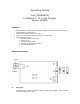


B. DC Output Wires
For connection to the battery to be charged (Connector is JST Male).
C. Cell Selection
3-Position switch located on the side of the charger. Reference above
diagram. Sliding the switch upwards towards “B” would be for One Cell
Charging, the Middle position is 2 Cell Charging, and the Bottom setting for 3
Cell Charging.
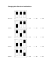
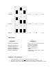
D. Charge Rate Selection
3-Position DIP switch provides the ability to choose appropriate charge
current. Chart provided later with possible settings defined.
E. Red LED
Charging Indicator
F. Green LED
Full Charge Indicator
Operational Process:
1. Connect the charger to DC power supply (DC10–15V). The Green LED will
flash. If the Red LED and Green LED are off, please check the power
connection polarity or that power is being supplied.
2. Confirm the Cell Selection setting: One, Two, or Three Cell configuration to be
charged.
3. Select the Charging Current according to the battery capacity. You should not
charge at more than 1C (1x capacity) or fire may result. For example, if you
are charging a 1400mAh Li-Po battery, then select the 1200 setting and not
the 1500 setting.
4. Connect the battery to the charger. If you notice
both LED’s flashing, there is
a problem with the power supply, polarity, or the battery voltage is too low to
charge (which indicates the battery may be damaged). If both LED’s are ON
solid, then check that the Charging Current mAh is not set to zero (0).
5. The charger’s Red LED is now on. If the Red LED is flashing, this indicates
pre-charging; if the Red LED is ON solid, this indicates normal charging.
Note: Pre-charging occurs if the battery voltage is too low as determined
by the charger; it will then slowly increase voltage, automatically switching to
normal charge.
6. When the Green LED comes ON, your battery is fully charged. Disconnect
charger from the battery.