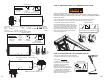
! INSTALLATION INSTRUCTIONS ! ! INSIDE THIS BOOK ! ! ! ! ! ! ! ! ! ! ! INSTRUCCIONES DE ! INSTALACIÓN EN ! ESTE LIBRO ! ! ! ! ! ! ! ! ! ! ! ! ! ATTIC LADDER INSTALLATION INSTRUCTIONS ! ! ! ! ! INSTRUCCIONES !DE INSTALACIÓN DE LA ESCALERA DE ÁTICO ! ! ! ! MODEL / MODELO: AL2212 ! ! ! ! (QJOLVK ,QJOpV $QJODLV 3DJH 6SDQLVK (VSDxRO (VSDJQRO 3DJH )UHQFK )UDQFpV )UDQoDLV 3DJH ! ! !
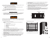
To prevent accidents, read all instructions completely before beginning this installation. Inspect the attic ladder for shipping damage and missing parts.
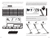
MINIMUM MATERIALS REQUIRED (not included) 1. Ladders 8. Two support boards 1” x 4” x 32” 2. Electric Drill and 1/8” Drill bit 9. Tape measure 3. Philips Head Screwdriver X2 10. Rubber mallet 4. Hex Head 7/16” Wrench X2 11. Wire cutters 5. Hack saw 12. Tin snips 6. Wood screws 2 1/2” 13. Safety glasses (recommended) DO NOT try to open the ladder. DO NOT remove plastic strap until instructed.
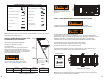
F. Attach temporary support boards “A” and “B” (1” x 4”x 32”) with 2-1/2” wood screws (not included). Support “A” will be 3” from the rough opening at the header/hinge end. Support “B” will be 8” from the rough opening at the footer end. Be sure to follow these board placement dimensions so the temporary support boards do not hinder the remaining installation steps. See Figures 5 and 5.1.
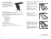
Materials needed in the attic: Lag Screws 3” (11) pcs Washers 1/4” (6) pcs Wood Screws 1 1/4” (2) pcs Figure 7.1 Shims Ladder Multipurpose Drill and 1/8” drill bit Hex Head 7/16” Wrench Phillips Head Screwdriver (Shims and tools not included) (Power tool alternative) G. Installer #2: Climb into the attic using an appropriate ladder (example: multipurpose, single ladder or extension ladder). Follow all instructions on this ladder.
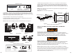
N. Installer #1: Remove the temporary wood support boards “A” and “B” from the ceiling. . See Figure 12. Materials needed: Footer NEVER USE DECK OR SHEETROCK SCREWS IN PLACE OF T THE E LAG SCREW SCREWS PROVIDED. Deck or sheetrock (drywall) screws are not ot suitable for fo supporting attic ladder loads. Temporary support “A” SECTIONS. DDER SECTION NS.
Materials needed: Lag Screws 3” (3) pcs STEP 4: FINALIZING THE ATTIC LADDER INSTALLATION Drill and Hex Head 1/8” Drill bit 7/16” Wrench (Not included) (Power tool alternative) DO NOT CLIMB ON THE ATTIC LADDER SECTIONS. Standing or climbing on the attic ladder’s climbing section prior to adjusting the ladder length and installing the aluminum feet could result in a fall and cause SERIOUS BODILY INJURY OR DEATH.
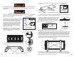
W. Reference the ceiling height you recorded in Section U and determine the location to cut the attic ladder side rails and feet for your ceiling height. See Table 4 and Figures 19 and Figure 19.1. Rail Cut Location: _______________ X. Installer #1: Press down on the top and middle sections of the attic ladder to ensure the door is open and the power arms are fully extended. Slide the aluminum foot over the ladder side rail as shown in Figure 20.
APPENDIX – Framing a rough opening parallel to ceiling height joist ADDITIONAL STEPS / INFORMATION: 1. Trim shims to prepare frame opening for finishing and to remove catch points and trip hazards. 2. The frame opening can now be finished. 3. Periodically lubricate (spray silicon recommended) pivot points of the right and left folding arm mechanisms (power arm assemblies) and every hinge to provide smooth, long-lasting operation. Follow arrows in Figure 24.
3DUD SUHYHQLU DFFLGHQWHV OHD ODV LQVWUXFFLRQHV FRPSOHWDPHQWH DQWHV GH LQLFLDU OD LQVWDODFLyQ ,QVSHFFLRQH OD HVFDOHUD GH iWLFR HQ EXVFD GH GDxRV HQ HO HQYtR R SLH]DV IDOWDQWHV x 5HYLVH OD SXHUWD GH PDGHUD SDUD YHU VL QR FXHQWD FRQ JULHWDV R GHIRUPDFLRQHV x 5HYLVH ODUJXHURV ODWHUDOHV GH OD HV x FDOHUD SHOGDxRV \ KHUUDMHV HQ EXVFD GH GDxRV WDOHV FRPR GREOHFHV IUDFWXUDV R JULHWDV x 5HYLVH TXH WRGRV ORV UHPDFKHV \ VXMHWDGRUHV HVWpQ DMXVWDGRV x 5HYLVH ORV NLWV GH ORV FRPSRQHQWHV LQFOXLGRV HQ OD 7DEOD x 5
12 LQWHQWH DEULU OD HVFDOHUD 12 UHPXHYD FLQWLOOR SOiVWLFR KDVWD TXH VH OH LQGLTXH PASO 1: INSTRUCCIONES DE INSTALACIÓN PRELIMINARES (67$ ,167$/$&,Ï1 5(48,(5( '( '26 3(5621$6 (1 72'2 020(172 ,QVWDODGRU WUDEDMDUi GHVGH HO SLVR H LQVWDODGRU WUDEDMDUi GHVGH HO iWLFR Tabla 2 +HUUDPLHQWDV \ HTXLSR QHFHVDULR SDUD OD LQVWDODFLyQ NOTA: 'H PDQHUD RSFLRQDO VH SXHGHQ XVDU KHUUDPLHQWDV HOpFWULFDV SDUD DFHOHUDU OD LQVWDODFLyQ (V SRVLEOH TXH VH QHFHVLWH XQD FXHUGD SDUD OHYDQWDU OD HVFDOHUD SRU OD DEHU
0DWHULDOHV QHFHVDULRV ) $VHJXUH ORV VRSRUWHV WHPSRUDOHV ³$´ \ ³%´ FP [ FP [ FP FRQ GRV SLMDV GH PDGHUD QR LQFOXLGDV 6RSRUWH ³$´ HVWDUi D ´ GH OD DEHUWXUD GHO WHFKR HQ HO H[WUHPR GHO FDEH]DO ELVDJUD 6RSRUWH ³%´ HVWDUi D ´ GH OD DEHUWXUD GHO WHFKR HQ HO H[WUHPR GH OD SLHFHUD $VHJ~UHVH GH VHJXLU HVWDV GLPHQVLRQHV GH FRORFDFLyQ GH WDEORQHV SDUD TXH ORV VRSRUWHV WHPSRUDOHV QR REVWDFXOLFHQ ORV SDVRV VLJXLHQWHV GH OD LQVWDODFLyQ 9HU )LJXUD \ NOTA: $VHJ~UHVH TXH ODV SLMDV GH
durante la instalación para iluminación o herramientas eléctricas. Antes de iniciar el trabajo, evalúe el área para asegurarse que su lugar de trabajo es seguro (riesgos por arriba de la cabeza, soportes en el suelo, calor, etc.). Figura 7.1 . $QWHV GH FRQWLQXDU HO LQVWDODGRU GHEH PHGLU HQ GLDJRQDO HO PDUFR GH DOXPLQLR SDUD DVHJXUDUVH TXH OD HVFDOHUD GH iWLFR HVWp HVFXDGUDGD /DV PHGLGDV $ \ $ GHEHQ PHGLU OR PLVPR KDVWD FRQ ´ GH GLIHUHQFLD HQWUH HOODV 9HU )LJXUD 6L QR OD SXHUWD GH OD HVFDOH
181&$ 86( 7251,//26 2 3,-$6 3$5$ 7$%/$52&$ (1 /8*$5 '( /$6 3,-$6 +(;$*21$/(6 3529,67$6 7RUQLOORV R SLMDV SDUD WDEODURFD QR VRQ DGHFXDGRV SDUD VRSRUWDU OD FDUJD GH OD HVFDOHUD GH iWLFR 12 6( 68%$ (1 /$6 6(&&,21(6 '( /$ (6&$/(5$ '( È7,&2 3DUDUVH R VXELUVH HQ ODV VHFFLRQHV GH OD HVFDOHUD GH iWLFR DQWHV GH DMXVWDU OD ORQJLWXG GH OD HVFDOHUD \ GH ORV WDFRQHV GHVOL]DEOHV SRGUtD UHVXOWDU HQ XQD FDtGD \ FDXVDU /(6,21(6 &25325$/(6 *5$9(6 2 /$ 08(57$ 0 ,QVWDODGRUHV \ &RQ HO FDEH]DO GH OD HVFDOH
5 &RQ OD SXHUWD DOLQHDGD FRQ HO PDUFR GH DOXPLQLR DEUD OD SXHUWD \ DVHJ~UHVH TXH ORV EUD]RV GH SRGHU HVWpQ FRPSOHWDPHQWH H[WHQGLGRV SDUD HYLWDU TXH OD SXHUWD VH FLHUUH LQHVSHUDGDPHQWH ,QVWDODGRU 3HUIRUH RULILFLRV JXtD GH ´ GH GLiPHWUR SRU ´ GH SURIXQGLGDG HQ ODV YLJDV GHO WHFKR D WUDYpV GH ORV WUHV RULILFLRV GHO FDEH]DO H LQVWDOH ODV SLMDV KH[DJRQDOHV HQ FDGD XELFDFLyQ 9HU )LJXUD 0DWHULDOHV QHFHVDULRV X: ´ 3LMDV KH[DJRQDOHV S]DV W: $UDQGHODV S]DV )LJXUD $VHJXUDQGR ULH
PASO 5: AJUSTANDO LARGO DE LA ESCALERA DE ÁTICO Pasos finales para completar la instalación de la escalera de ático. 8 ,QVWDODGRU 0LGH \ UHJLVWUH OD DOWXUD GH WHFKR $OWXUD GH WHFKR BBBBBBBBBBB FigurD 19: 8ELFDFLyQ SDUD FRUWD ODUJXHUR ODWHUDO 9 Instalador #1: AHORA PUEDE QUITAR EL CINTILLO PLÁSTICO QUE SOSTIENE JUNTAS LAS SECCIONES DE LA ESCALERA DE ÁTICO. Con las pinzas cortacable, remueva el cintillo plástico que sostiene las secciones de la escalera en posición cerrada.
APENDICE – Enmarcando la abertura paralela a las vigas del techo +DJD XQD DEHUWXUD HQ HO WHFKR DSUR[LPDGDPHQWH GHO WDPDxR UHTXHULGR HQ OD 7DEOD DVHJ~UHVH TXH ODV GLPHQVLRQHV GH ODV GLDJRQDOHV GHO PDUFR VHDQ LJXDOHV D FRPR VH PXHVWUDQ HQ OD )LJXUD A. Para la abertura sin necesidad de remover vigas del techo. 9HU )LJXUD /RFDOLFH ORV FDEH]DOHV HQ OD SDUWH GHODQWHUD \ WUDVHUD GH OD DEHUWXUD D FRPR VH PXHVWUD HQ OD )LJXUD $VHJXUH OD FXDGUDWXUD DVHJXUiQGRVH GH TXH ODV PHGLGDV HQ GLDJRQDOHV
5. AVERTISSEMENT Pour éviter tout accident, lisez entièrement toutes les instructions avant de commencer l’installation. Inspectez l’échelle de grenier afin de déceler tout dommage survenu pendant le transport et toute pièce manquante. • Vérifiez le panneau de porte en bois afin de déceler toute fente ou déformation. • Vérifiez les montants latéraux, les barreaux et la quincaillerie de l’échelle afin de déceler tout dommage comme les courbures, les fentes ou les fissures.
MINIMUM MATERIALS REQUIRED (not included) 1. Échelles 8. Deux (2) planches de soutien de 1 po sur 4 po sur 32 po 2. Perceuse électrique et mèche de 1/8 po 9. Ruban à mesurer Étiquette d’instructions Étiquette du modèle sangle 3. Tournevis à tête phillips X2 10. Maillet en caoutchouc 4. Hexagonale de 7/16 po X2 11. Pince coupe-fils 5. Scie à métaux 12. Cisaille de ferblantier 6. Vis à bois de 2 1/2 po 13.
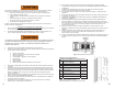
Vous devez disposer d’une ouverture qui correspond aux indications du tableau 3. Sinon, rendez-vous aux instructions de l’annexe pour adapter la charpente. MODÈLE OUVERTURE No DE PRODUIT 22 1/2 po sur 54 po PLAGE DE HAUTE DU PLAFOND « A » 7 pi 9 po à 10 pi 3 po EMPLACEMENT DE RÉCEPTION «B» RAYON D’OUVERTURE «C» 66 po* 75 po *À une hauteur maximum de plafond de 10 pi 3 po Tableaux 3 Exigences d’installation AVERTISSEMENT N’essayez PAS d’ouvrir l’échelle.
Tenez fermement la sangle métallique pour éviter qu’elle ne tourne pendant que vous vissez la pièce de fixation dans le cadre en aluminium. D. Répétez l’installation de la deuxième sangle sur le côté opposé. E. Positionnez les deux sangles verticalement comme l’illustre la figure 4.1. Repliez les deux sangles vers l’intérieur, sur la section des barreaux, pour les dégager. Consultez la figure 4.2. REMARQUE : NE laissez PAS les sangles en métal dépasser le cadre en aluminium. Consultez la figure 4.3. F.
AVERTISSEMENT L’OUVERTURE PRÉSENTE UN RISQUE DE CHUTE. L’installateur nº 2 travaille temporairement autour d’une ouverture dans le plancher et pourrait tomber. Il doit prendre les précautions nécessaires pour garder son équilibre et se tenir à une distance sûre de l’ouverture, lorsque cela est possible. L’installateur nº 2 ne doit PAS ranger de matériel sur l’échelle du grenier ou sur la porte du grenier, puisque ce matériel pourrait tomber quand on ouvre la porte.
Rondelle Sangles en métal Vis à bois Tirefond Cadre en aluminium Figure 9 Planche de soutien Figure 9.1 Vis à bois AVERTISSEMENT Figure 10 Fixation des pieds de l’échelle de grenier REMARQUE : Assurez-vous de ne percer que dans les trous qui comportent des garnitures. Consultez la figure 11. Pieds N’UTILISEZ JAMAIS DE VIS POUR TERRASSE OU POUR CLOISON SÈCHE POUR REMPLACER LES TIREFONDS FOURNIS.
Nœud X: Vis auto-foreuses de 3 po (3) Rondelle Porte Corde X X Rondelle Corde Figure 13 X Figure 15 Fixation du linteau de l’échelle de grenier IMPORTANT : Si le cadre n’est pas d’équerre, la porte du grenier risque de ne pas bien fermer. Figure 13 Fixation de la corde Q. Installateur nº 1 : Ouvrez et fermez plusieurs fois la porte de l’échelle de grenier pour vous assurer qu’elle est centrée dans l’ouverture du cadre et que le tout est d’équerre. Consultez la figure 14.
ÉTAPE 4 : FINALISATION DE L’INSTALLATION DE L’ÉCHELLE DE GRENIER Dernières étapes pour terminer l’installation de l’échelle de grenier. AVERTISSEMENT U. Installateur no 1 : Mesurez et consignez la hauteur du plafond. NE GRIMPEZ PAS SUR LES BARREAUX DE L’ÉCHELLE DE GRENIER. Le fait de se tenir debout ou de grimper sur les barreaux de l’échelle de grenier avant d’ajuster la longueur de l’échelle et d’installer les pieds en aluminium pourrait provoquer une chute et causer des BLESSURES GRAVES OU MORTELLES.
27” 15” Barreau 1 : Couper la ligne non indiquée sur le montant 3” B A Barreau 2 : Couper la ligne non indiquée sur le montant C Barreau 3 : Couper la ligne non indiquée sur le montant Figure 19 Endroits où couper les montants de l’échelle E E D D Y. Installateur no 1 : Assurez-vous que les joints ne sont pas ouverts entre les sections de l’échelle et que les deux pieds reposent sur le plancher. Quand elle est correctement ajustée, l’échelle de grenier doit ressembler à ce qu’illustre la figure 22.
ANNEXE – Préparation d’une ouverture parallèle à une solive de plafond Faites une ouverture aux dimensions indiquées au tableau 3 en veillant à ce que les dimensions des diagonales du cadre soient identiques à celles illustrées à la figure 25. ÉTAPES/INFORMATION SUPPLÉMENTAIRES : 1. Couper des cales afin de préparer l’ouverture du cadre pour la finition et d’éliminer les points d’accrochage et les risques de trébuchement. 2. Vous pouvez maintenant finir l’ouverture du cadre. 3.