
Instructions / Assembly

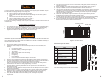
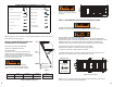
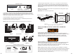

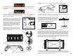
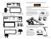
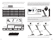
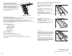
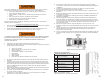

Table 2 Tools and equipment needed for installation
NOTE:
Alternatively, power tools may be used to expedite installation. A rope may be needed to
lift the ladder into the rough opening.
INSTALLATION INSTRUCTIONS FOR
ALUMINUM ATTIC LADDERS
READ INSTRUCTIONS AND WARNINGS
COMPLETELY BEFORE STARTING.
Attic ladder location:
Allow ample room for the swing clearance and the
landing space of the folding attic ladder when it is
opened. (See Figure 2 and Table 3). Locate the folding
attic ladder rough opening so that you
ha
ve adequate
head clearance and walking area.
Exercise caution around this opening.
You must have a rough opening that matches
Table 3. If not, proceed to Appendix for framing.
MODEL
ROUGH
OPENING
CEILING HT
RANGE “A”
LANDING
SPACE “B”
SWING
CLEARENCE “C”
AH2211 22 ½” X 54” 7’ 9” – 10’3” 66”* 75”
*At maximum ceiling height of 10’3”
Table 3 Installation requirements
DO NOT try to open the ladder.
DO NOT remove plastic strap until
instructed.
STEP 1: PRELIMINARY INSTALLATION INSTRUCTIONS
THIS INSTALLATION REQUIRES TWO PEOPLE AT ALL TIMES.
Installer #1 will work from the floor and Installer #2 will work from the attic.
DO NOT INSTALL DURING EXTREME HEAT.
Temperatures in attics can be much hotter than home and outside temperatures.
Extreme heat in attics can cause heat exhaus
tion
(e.g., dizziness, headaches, severe
sweating, dehydration, cramps) that may impede your ability to complete this
installation. Stay in verbal contact with the other installer and stay well hydrated.
The
following instructions explain the tasks for each installer.
Prepare the attic ladder for installation into the rough opening.
A. Posi
tion the attic ladder on a flat horizontal work surface.
B. Install the plastic bushings by pressing or tapping
l
ightly with a rubber mallet into the pre-
drilled holes on the aluminum frame in the positions shown in Figure 3.
NOTE: Be sure each plastic bushing is fully inserted and aligned in the holes, otherwise they
may become loose or damaged during the installation.
Plastic Bushings
(11) pcs
Rubber Mallet
(Not included)
Materials needed:
Figure 2
Fi
g
ure 3 Bushin
g
locations
3 4
CEILING
HEIGHT
RANGE
FLOOR
CEILING
LANDING SPACE
SWING CLEARENCE
Strap
8. Two support boards 1” x 4” x 32”
7. Shim
13. Safety glasses
(recommended)
1. Ladders
MINIMUM MATERIALS REQUIRED (not included)
4. Hex Head 7/16” Wrench
9. Tape measure
12. Tin snips
5. Hack saw
3. Philips Head Screwdriver
X2
X2
6. Wood screws 2 1/2”
2. Electric Drill and 1/8” Drill bit
10. Rubber mallet
11. Wire cutters