
Instructions / Assembly
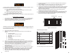

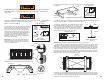
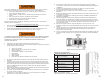

C. Unfold the 14” metal straps. Place a self-drilling screw through the bottom 1/4" diameter
(large) strap hole. Position one metal strap flat against the side of the aluminum frame and
between the two rivets as shown on Figures 4 and 4.1. Hold the metal strap securely to resist
rotation while screwing the fastener into the aluminum frame.
D. Repeat installation of the second strap on the opposite side.
E. Position both straps vertically as shown in Figure 4.1. Fold both straps in
ward over the
cl
imbing section and out of the way. See Figure 4.2.
NOTE: DO NOT let the metal straps extend below the aluminum frame. See Figure 4.3
Strap
installation
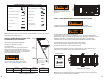
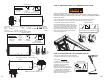
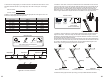
F. Attach temporary support boards “A” and “B” (1” x 4”x 32”) with 2-1/2” wood screws (not
included). Support “A” will be 3” from the rough opening at the header/hinge end. Support “B”
will be 8” from the rough opening at the footer end. Be sure to follow these board placement
dimensions so the temporary support boards do not hinder the re
mainin
g installation steps. See
Figures 5 and 5.1.
NOTE: Be sure all temporary support board screws penetrate into the ceiling joists to support
the weight of the attic ladder.
IMPORTANT: Never use deck or drywall screws.
Temporary support board installation
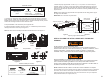
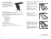
STEP 2: PLACING THE ATTIC LADDER INTO THE ROUGH
OPENING
DO NOT INSTALL DURING EXTREME HEAT.
Temperatures in attics can be much hotter than home and outside temperatures.
Extreme heat in attics can cause heat exhaustion (e.g.,
dizzine
ss, headaches, severe
sweating, dehydration, cramps) that may impede your ability to complete this
installation. Stay in verbal contact with the other installer and stay well hydrated.
ROU
GH OPENING IS A POSSIBLE FALL HAZARD.
Installer #2 is temporarily working around a floor opening and could fall. Appropriate
care is needed to maintain good balance and to keep a safe distance from the
opening when possible. Installer #2 should NOT store materials on
the attic ladder or
the attic door as materials may fall when opening the door.
NOTE: I
nstaller #2 will be unable to exit the attic until the installation is complete.
Be sure installer #2 has all the materials and tools needed to complete the tasks to be performed
from above. Be sure there is electric power (or batteries) for the duration of the installation for
lighting and power tools. Before beginning work, assess the area to be sure your workplace is
safe (overhead
hazards, floor support, heat, etc.).
Metal Straps 14”
(2) pcs
Self-Drilling
Screws (2) pcs
Materials needed:
Phillips Head
Screwdriver
(Power tool alternative) (Not included)
Figure 4
Fi
g
ure 4.1
Figure 4.2
Fi
g
ure 4.3
Wood Screws
2 1/2” (4) pcs
Support Boards
(2) pcs
Phillips Head
Screwdriver
Ladder
Materials needed (Not included):
(Power tool alternative)
Figure 5
Fi
g
ure 5.1
5 6
Screw
head
Metal straps 14”
Temporary support “A”
Temporary support “A”
Temporary support “B”
Temporary support “B”
Wood screws
(2) per board
Wood screws
(2) per board
Rough Opening
Footer
Header
3"
8"