
Instructions / Assembly


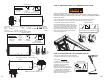

NEVER USE DECK OR SHEETROCK SCREWS IN PLACE OF THE LAG SCREWS
PROVIDED. Deck or sheetrock (drywall) screws are not suitable for supporting attic
ladder loads.
DO N
OT CLIMB ON THE ATTIC LADDER SECTIONS.
Standing or climbing on the attic ladder’s climbing section prior to adjusting the ladder
length and installing the aluminum feet could result in a fall and cause SERIOUS
BODILY INJURY OR DEATH
.
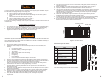
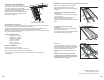
M. Installers #1 and #2: With the header end of the attic
ladder supported by the metal straps, the footer end can
now be secured. Check the shims positioned at the
foo
ter end to be sure they are still centered at the pre
-
drilled locations. Installer #2: Drill 3” deep pilot holes
through the shims and into the ceiling joists and install
two 3” lag screws and washers at each location to
permanently secure the attic ladder. See Figure
10.
Installer #1: Hold the shims securely to resist rotation
during drilling and screwing.
IMPORTANT:
Do not force or deform the aluminum
frame with the shims. This may cause an un-square
condition
. If
the frame is not properly square the attic
door may
not close properly.
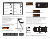
NOTE:
Make sure to drill through the holes with bushings only.
See figure 11.
.
Figure 11
Drilling pilot holes at Footer end
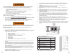
O. Installer #2: Make sure no materials are stored on the
attic
ladder door as these may fall when
opening the door. Installer
#1: Carefully open the attic ladder door.
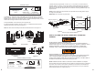
P. Installer #1: Thread the 36” pull cord through the pre-drilled
hole in the attic ladder door. Place the 1/4” x 1” washer on the
top
sid
e of the attic door panel and tie a knot in the end of the
cord. The length of the cord can be adjusted after the ladder
is completely installed. Be sure the knot is large enough, so it
does not slip back through the hole. See Figure 13.
IMPORTANT:
If the frame is not square the attic door may not close properly.
Q. Installer #1: Open and close the attic ladder door several times to ensure the door is
centered
within the frame opening and the unit is square. See Figure 14. Installer #1 and #2:
If the
attic
ladder frame is not square, position shims between the attic ladder side frame and ceiling joist.
Placing shims at the header end on one side of the frame will allow the header end of the frame
to be moved slightly and square the ladder. Installer #1: Open and close the attic ladder door
several times to ensure the door is centered within the fame opening. If necessary, continue to
adjust the aluminum frame in the rough opening by slightly moving the header/hinge end side to
side until the door closes cleanl
y into the fram
e opening.
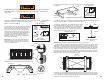
R. With the door now in alignment with the aluminum frame, open the door and make sure the
power arms are fully extended to avoid unexpected door closure. Installer #2: Drill 1/8” diameter
by 3” deep pilot holes into the ceiling joist through the three pre-drilled holes in the header and
install the 3” lag screws in each location. See Figure 15.
Figure 10 Securing the footer end of the attic ladder
E
L
AG
S
CR
EW
s
up
p
ortin
g
attic
Lag Screws
3” (2) pcs
P
L
AC
E
OF
T
ot
s
ui
t
ab
le
f
o
Washers
(2) pcs
D
DER
S
E
C
TI
ON
e
Drill and
1/8” drill bit
NS
.
Hex Head
7/16” Wrench
Materials needed:
cti
on
prior to adjusti
ng
th
e
l
adde
r
n
a
fa
l
l
a
nd
c
au
s
e
S
ERI
OUS
c
ti
on
prior to ad
(Not included)
(Power tool alternative)
Figure 13 Securing the
pull cord
Pull Cord 36”
pu
ll cord
t
hr
ough
t
he
pr
Washer 1/4” (1) pc
Materials needed:
Figure 14 Squaring the attic ladder
9 10
Washer
Lag screw
Footer
Knot
Door
Washer
Pull cord
Footer
Temporary
support “B”
Temporary
support “A”
Do not drill on any other
location per corner
Drill through
bushing holes
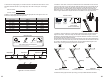
N. Installer #1: Remove the temporary wood support boards “A”
and “B” from the ceiling.
See Figure 12.
.
Phillips Head
Screwdriver
Materials needed:
(Not included)
Fi
g
ure 12 Removin
g
the tem
p
orar
y
su
pp
ort boards
(Power tool alternative)
A2
A1
A1 = A2