
Instructions / Assembly


(Not included)
(Power tool alternative)
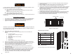
Lag Screws
3” (3) pcs
Drill and
1/8” Drill bit
Hex Head
7/16” Wrench
Materials needed:
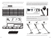
S. Installer #1 and #2: Position shims from above and below at the six remaining pre
-
drilled
holes, three in each frame side rail. See Figure 16. Shims should provide uniform support so
there is no twisting or bowing of the aluminum frame. Drill 1/8” diameter by 3” deep pilot holes
into the ceiling joist through the pre-drilled holes. Install the six lag screws and the two washers
(where indicated in Figure 16.1) to secure the attic ladder.
F
igure 16 Shimming side frame
X:
3” Lag scr
ew (6) pcs W:
Washer (2) pcs
STEP 4: FINALIZING THE ATTIC LADDER INSTALLATION
DO NOT CLIMB ON THE ATTIC LADDER SECTIONS.
Standing or climbing on the attic ladder’s climbing section prior to adjusting the ladder
length and installing the aluminum feet could result in a fall and cause SERIOUS BODILY
INJURY OR DEATH.
These remaining instructions are necessary to ensure the attic ladder climbing section is
properly supported for use and possible obstructions and catch points are removed.
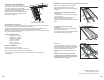
T. Installer #2: With the aluminum attic ladder
frame secured and the door open, remove the
wood screws from the metal straps. Cut the metal
straps as close as possible to the aluminum frame.
Be careful of any sharp edges. Turn any excess
strap material down between the aluminum frame
and the rough opening to eliminate a possible
catch point. See Figure 17.
Figure 17 Removing excess metal strap material
STEP 5: ADJUSTING THE ATTIC LADDER LENGTH
Final steps to complete the attic ladder installation.
U. Installer #1: Measure and record the ceiling height.
Ceiling Height:___________
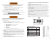
V. Installer #1: YOU MAY NOW
REMOVE THE PLASTIC STRAP
HOLDING THE ATTIC LADDER
SECTIONS TOGETHER.
With wire cutters, remove the plastic
strap that is holding the ladder sections
in a closed position. Carefully unfold
the ladder sections to the ground.
Position the bottom section behind the
middle section. See Figure 18.
(Not included)
(Power tool alternative)
Lag Screws
3” (6) pcs
Washers
(2) pcs
Drill and
1/8” drill bit
Hex Head
7/16” Wrench
al
ler
#1 and #2
: Position shims
f
rom
abo
ve
and be
low at
t
he
si
x
remaining pre
d
t
h
r
ee
i
n
ea
ch
f
ra
me
s
i
d
e
ra
il
.
S
ee Fi
g
ur
e
1
6
.
S
him
s
s
ho
u
ld provide
un
if
or
m
s
gp
u
pp
s
no
twistin
g
or
bo
wing of
t
f
he
a
l
u
mi
nu
m
f
r
ame. Drill 1
/
8” diameter b
y
3” dee
p
pil
o
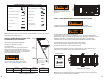
Materials needed:
Figure 16.1 Securing side frame rails
Materials needed:
(Not included) (Power tool alternative)
Phillips Head Screwdriver
lalter
na
tive)
r Tin snips
Tape Measure
a
sur
e
Wire cutter
Materials needed:
(Not included)
Figure 18 Unfolding
ladder sections
11 12
Shim
Shim
Shims
Support
board
Support
board
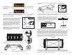
12 3
45
X
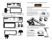
Pivot Plate
Washer
Washer
Lag screw
Pivot Plate
X
W
XX
W
X
X
6
Remove screw Rotate strap
X
X
X
Figure15: Securing the header end of the attic ladder
X: 3” Lag screw (3) pcs