
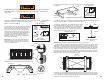
Instructions / Assembly

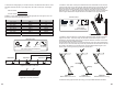
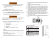

W. Reference the ceiling height you recorded in Section U and determine the location to cut the
attic ladder side rails and feet for your ceiling height. See Table 4 and Figures 19 and Figure
19.1.
Rail Cut Location: _______________
Fo
ot Cut Location: _______________
Installer #1: Cut the ladder side rails and feet at the appropriate line. See Figures 19 and 19.1.
Be careful of sharp edges after making the cuts.
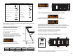
CEILING HEIGHT RAIL CUT FOOT CUT
7' 9"- 7' 10" Step 3 E
7' 11"- 8' Rail C E
8' 1"- 8' 3" Rail C D
8' 4"- 8' 6" Rail B No cut
8' 7"- 8' 11" Step 2 No cut
9' - 9' 5" Rail A No cut
9' 6" - 9' 8" Step 1 No cut
9' 9" - 10' 3" No cut No cut
Table 4 Rail and foot cut locations
Figure 19 Cut location, ladder rails
Figure 19.1 Cut location, ladder feet
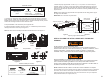
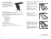
X. Installer #1: Press down on the top and middle sections of the attic ladder to ensure the door
is open and the power arms are fully extended. Slide the aluminum foot over the ladder side rail
as shown in Figure 20. Position it so the rubber foot pad is in contact with the floor. Again, be
sure the power arms are fully extended. Align the aluminum shoe with the closest s
et of pre-
dri
lled holes. Use (2) 1/4” bolts and serrated nuts to attach the aluminum shoe to the attic ladder
side rail. Tighten both fasteners. Repeat aluminum foot installation on the opposite side rail.
F
igure 20 Aluminum foot installation
Y. Installer #1: Verify that there are no gaps between the ladder sections and that both feet are
supported on the floor. Trimmed correctly, the attic ladder should look like Figure 22. Minor
adjustments to eliminate ladder section gaps and to position both fee
t on the floor can be made
by re-positioning the feet in different rail holes.
If the attic ladder looks like Figure 21, then the bottom section is too short, and the attic ladder is
not safe to use. A new lower section may need to be purchased from the manufacturer if the feet
are not able to be adjusted to new mounting holes. If the attic ladder looks like Figure 23, the
bottom section is too long and the legs need to be trimmed further.
Z. Installer #2: Safely egress the attic space using your newl
y i
nstalled aluminum attic ladder.
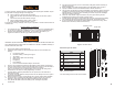
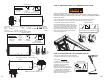
Tape Measure Hack Saw
Materials needed:
(Not included) (Power tool alternative)
t
oo
oo
lalter
na
tive)
Hex Head 7/16” Wrench
X2
Bolts 1/4” x
3/4” (4) pcs
1/
4”
x
4)
pcs
Nut 1/4”
(4) pcs
Materials needed:
Hex Head
7/16” Wrench
(Not included)
(Power tool alternative)
13 14
E
D
DE
Gap No Gap
No Gap
Figure 21
Bottom section is too short
Figure 22
Feet flush with floor
Figure 23
Bottom section is too long
Gap
A
B
C
27”
Step 2: Cut line
not marked on rail
Step 3: Cut line
not marked on rail
Ladder feet: Cut when required
15”
3”
Step 1: Cut line
not marked on rail