
Manual


Instruction Sheet
IS-MA60/125/250
Issued: 5-1-14
Lowell Manufacturing Company
100 Integram Drive Pacific, Missouri 63069 U.S.A.
Call: 800-325-9660
Fax: 636-257-6606 Click: www.lowellmfg.com
7
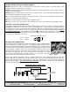
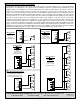
TELEPHONE CHANNEL INPUT WIRING
GND
_
+
TELEPHONE INPUT
OF AMPLIFIER
From the
Telephone
System
Page-Port
Output
600W Twisted-Pair Wiring
Shielded wiring from the telephone system is typically not required, but if
shielded wiring is used, drain the shield at the telephone input and butt
the shield (no connection) at the telephone system page port output.
BUTT
SHIELD
(No connection)
Special Channel 6
Channel-6 (aux inputs only) are all muted by the Telephone input and by the Channel-1 input if the Channel-1 mute
. Channel-6 has no mic inputs. The Channel-6 (Aux 6) level control is located to the
left of the AUX 6 RCA-Phono input jacks. The Channel-6 aux inputs never mute any other channels.
Muting Priority 3
Channels-3, Channel-4, and Channel-5 (the XLR inputs, screw terminal inputs, and aux inputs) are all muted by the
telephone input and by the Channel-1 input if the Channel-1 . Channel-3,
Channel-4, and Channel-5 never mute any other channels.
Special Channel 2
Channel-2 (XLR input, screw terminal inputs and aux inputs) are all muted by the telephone input. Channel-2,
however, is never muted by any other channel including Channel-1. The Channel-2 inputs never mute any other
channels, so Channel-2 can be treated as a special input channel that is not affected by any mutes, except the mute
from the telephone input.
Muting Priority 2
The Channel-1 XLR or screw terminal inputs (not the Channel-1 aux inputs) have the second highest level of muting
priority. The telephone input always mutes Channel-1. The Channel-1 XLR and screw terminal inputs mute
Channels 3-6 as long as the Channel-1 . The Channel-1 muting is active
whether using the XLR or screw terminal inputs in the microphone mode (1),
or when using the XLR or screw terminal inputs in the balanced line level mode (1
position). Channel-1 never mutes the Channel-2 inputs.
Muting Priority 1
The telephone input Channel-7 has the highest level of muting priority. The telephone input is never muted by other
inputs and the telephone input mutes all other inputs. The muting caused by the telephone input is not defeatable
(in other words, the muting is always on).
AMPLIFIER MUTING-PRIORITY SCHEME
The amplifier includes unique voice-activated (VOX) ducking/muting circuitry. When a page is made, other inputs
(such as a music input) that are set up at a lower muting level, softly lower in volume during the page. If the volume
of the page is not strong, the music will only duck in volume (not be completely muted). If the incoming page is
strong in level, the music volume will be completely muted. When the page has been completed, the volume of the
music will return to its normal level. The amplifier has three levels of muting priority as described below:
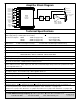
TELEPHONE INPUT CHANNEL
The amplifier includes a telephone input Channel-7. This input accepts a low impedance balanced 600W line level
input that would typically be available as a page port output from a telephone system. A Channel-7 level control is
located on the rear panel directly to the right of the telephone input terminals.
DRAIN
SHIELD