Model No. MP16 Amplified Monitor Panel User Manual Sixteen channels of visual monitoring and 16 x 1 selectable aural monitoring through choice of line or speaker levels per channel. © Lowell Manufacturing Company, 100 Integram Dr., Pacific, Missouri 63069 U.S.A., ph. 800.325.9660 www.lowellmfg.com Lowell makes every effort to provide accurate information and reserves the right to change specifications and/or improve manufacturing methods without notice. 11.03.
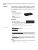
Immediately upon receipt of equipment, carefully inspect the shipping container and contents for damage. Immediately report any damage to the freight company and dealer/Lowell. Carton contents: MP16 amplified monitor, power supply module (with attached cord and connector), user manual I. DESCRIPTION: The MP16 amplified monitor is a 16 channel audio level display panel and a selectable (1 of 16 channels) audio monitor.
Electrical: • Power requirements: 18 volts AC, 50 to 60 Hz 2 amperes or 18 volts DC, 1.25 amperes. Power adapter module to convert 120 volts AC to 18 volts AC is included. • Signal Inputs: Input Impedances: Input switch at 77 millivolts (0.070 volts), impedance = 40 kilohms Input switch at 775 millivolts (0.70 volts), impedance = 400 kilohms Input switch at 70.7 volts, impedance = 40 megohms Input voltages, nominal (factory settings): 77 millivolts, 775 millivolts, 70.
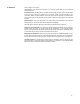
3 MP16 rear panel — connections and settings
IV. OPERATION: Refer to diagram on next page. Check Power: Verify that the unit is powered (1 of 16 channel selector LEDs on top of front panel should be lit green). Set Voltage Levels: The MP16 has 16 (3-position) switches on the rear panel. These switches set the monitor to receive 3 ranges of voltage levels (77 millivolts –20dBu, 775 millivolts–0dBu or 70.7 volts–about +40dBu).
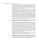
5 MP16 front panel — indicators and controls
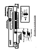
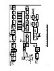
V. THEORY of OPERATION: Refer to diagram on next page. Description: The MP16 amplified monitor is a 16 channel audio level display panel and a selectable (1 of 16 channels) audio monitor. Ten levels of audio are displayed on a vertical array of colored LEDs (4 green, 1 yellow, 1 red). Each channel has a 3-position level selection switch (0.077, 0.775, and 70.7 volts) on the rear panel. These are the levels that are nominally displayed at the 0dB LED (factory settings).
7 MP16 block diagram — bar display
VI. MAINTENANCE: Restoring factory settings to front panel pots: 1. Input a 0dBu (0.775 volts) 1 kilohertz sine wave signal into the rear panel channel terminal block for the channel to be adjusted. 2. Set the rear panel selector switch for that channel to the switches midposition. 3. Adjust the front panel pot for that channel so that the 0dB LED for that channel just lights. Restoring factory settings to LINE OUT TRIM, RV901: 1. Input a 0dBu (0.