
Owner's manual


Electrical:
• Power requirements: 18 volts AC, 50 to 60 Hz 2 amperes or 18 volts DC, 1.25 amperes. Power
adapter module to convert 120 volts AC to 18 volts AC is included.
• Signal Inputs:
Input Impedances:
Input switch at 77 millivolts (0.070 volts), impedance = 40 kilohms
I
nput switch at 775 millivolts (0.70 volts), impedance = 400 kilohms
Input switch at 70.7 volts, impedance = 40 megohms
Input voltages, nominal (factory settings): 77 millivolts, 775 millivolts, 70.7 volts, depending on po-
sition of input switch. The headroom is 9dB. (Front panel adjustment can change these numbers.)
• Signal Output
:
Output Impedance: Balanced, 600 ohms
Output Level: 0dBu (factory setting when input switch is in center position, and 0dBu, 1kHz signal
is input).
• Speaker Amplifier Output:
Power: 10 watts into 3.2 ohms.
• Headphone Jack Output: Caution: Lower the volume BEFORE putting on headphones. Four
volts rms open circuit, maximum, 100 ohms output impedance peroutput (of two outputs). Output
into 32 ohms: 1 volt rms One volt rms at 32 ohms is approximately 30 milliwatts, SPL ~ 109dB)
Depending on level and duration, noise, sound or music can be a minor irritant, disturbance or
threat to hearing. Federal, state, and local agencies have established standards for how much
noise, sound or music is acceptable. The table below is extracted from U.S. Department of Labor
noise regulations.
Sound level (dB), A-weighting, SLOW response Duration per day (hours)
90 8
95 4
100 2
105 1
110 1/2
115 1/4
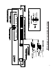
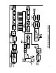
III. INSTALLATION: Refer to diagram on next page.
Mechanical: Thel MP16 can be rack-mounted in 2RU panel space. The power supply for the MP16 is a
desktop unit. Mechanically secure the power supply so the plug stays in the wall.
Electrical: Connections to inputs via 2-pin plug-in terminal blocks (plug in rear panel).
Power: The output of the power supply module plugs into the rear panel DIN connector.
Input Signal: Terminal blocks TB1 and TB2 are the inputs. Since the terminal blocks are 2-piece, the plug
part can be pre-wired before it’s plugged into rear panel terminal blocks. The connection for each channel
is a pair of terminals. The shield, if present, should be terminated at its other end, or, if required at the
MP16 end, daisy chain the shields and connect them to chassis/earth. The terminal blocks accept a range
of wire sizes from 30 AWG to 12 AWG.
Setting Levels:
• Access: Remove the lower half of the rear panel by unscrewing 2 thumb screws on either side. Set
the selector switch for each channel for the expected input level. Use the illustration on rear panel as
a guide.
• Output Signal (“LINE OUT”) (Line level, balanced, 600 ohm at TB901):
Wire the two contact terminal block plug and plug it in. The terminal blocks accept a range of wire
sizes from 30 AWG to 12 AWG. A shield can be tied as above or at the other end of the wiring run.
2