
Owner's manual
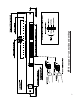

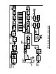
V. THEORY of OPERATION: Refer to diagram on next page.
D
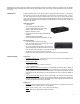
escription: The MP16 amplified monitor is a 16 channel audio level display panel and a selectable (1
of 16 channels) audio monitor. Ten levels of audio are displayed on a vertical array of colored LEDs (4
green, 1 yellow, 1 red). Each channel has a 3-position level selection switch (0.077, 0.775, and 70.7
volts) on the rear panel. These are the levels that are nominally displayed at the 0dB LED (factory set-
tings). Level settings for each channel are user-adjustable over a wide range at an individual trimmer
o
n the front panel. The MP16 is housed in a 2RU chassis.
Signal to Display Path: The top of the block diagram on the next page shows, as an example, Channel
1 of the 16 channels. The bottom of the block diagram shows circuitry common to all 16 channels. An
example: A balanced 77 millivolt (-20dBm) audio signal is connected to the terminal block. The three
position selector switch is set to the most sensitive position. The minimum attenuation is ½ or 6dB, and
the signal presented to U101, differential input amplifier, is 77/2 millivolts. The amplifier has a gain of 5
(14dB) which bosts the level to 192.5 millivolts. Assuming the front panel pot, RV102, is at maximum,
the single ended level at Buffer Amp U105A is 192.5 millivolts. Passing through U105A, the signal be-
comes six times larger or 1.155 volts. The peak to peak level of 1.155 volts rms is 3.266 volts. This
signal is presented to both the Half Wave Rectifier and the 1 of 16 demultiplexer. The Half Wave Rectifier
has a effective gain of 2 times ½ of the signal which is now 1.65 volts DC. The signal is then filtered
with a filter that has a time constant of 1 millisecond. The signal now goes to the LED Display Driver,
U104, which has its reference set at 4.28 volts, nominal. The voltage, 4.28 volts, represents the maximum
level, +9dBu. A voltage of 1.50 volts represents 0dBu. The factory setting of the front panel pot RV102
reduces the 1.65 volts DC to 1.50 volts so that the 0dB LED is just turned on.
Demultiplexer: The channel one signal reaching the demultiplexer is selected by the front panel push-
button switches. The output signal of the demultiplexer travels in two paths: one towards the
headphone/speaker amplifier and the sother towards the line level signal amplifier.
Balanced Line Level 600 ohm Output: The signal towards the line level amplifier is applied to pot
RV901 which sets the balanced output line level. The signal travels from RV901 wiper to U904A, which
has a gain of 4. The signal is now inverted by U904B and sent via two 300 ohm build-out resistors to
the output terminal strip, TB901. Pot, RV901, is adjusted to give a balanced output at TB901 of 0dBu.
Loudspeaker and Loudspeaker Amplifier (Power Amplifier): Digital volume control is provided on
the front panel to set the relative listening level with 40dB of control. While it does not provide an absolute
“off” (meaning silence), it’s meant to set the relative listening level. From the demultiplexer, U903, the
audio signal goes to pot RV902. This pot is set to prevent clipping at Speaker Amplifier U901, when the
Digital Volume Control U902 is at maximum. The wiper of pot RV902 goes to Digital Volume Control
U902. The output of U902 drives the input of Power Amplifier U901. U901 the loudspeaker, and through
a pad, drives the headphone jack. The gain of the Power Amplifier U901 is 11. The Power Amplifier pro-
duces a power of 10 watts into the 3.2 ohm speaker. The output at the headphone jack is 30 milliwatts,
producing a sound pressure level (SPL) of 109dB.
Loudspeaker Front Panel On/Off Switch: The front panel speaker switch is an illuminated push-type
single pole double throw switch. The switch enables the speaker by supplying a ground to the speaker,
while simultaneously removing the ground from the LED (allowing it to light).
Power Supply: A table mount 18 volts DC supplies DC to a 3.6 ampere regulator. The regulator is
followed by a capacitor filter. From the filter, power flows to regulators U914 and U909. The U914 supplies
15VDC to the speaker amplifier (“Power Amplifier”) only. The U909 supplies +12VDC power to the
analog circuitry and to regulators U910 and U911. The U910 supplies the digital 5VDC and U911 supplies
the analog 6VDC analog midvoltage. The digital 5VDC also powers front panel LEDs.
6