
Manual

ULDWB82T572
ASSEMBLY
INSTALLATION SHEET #IS-ULD
ULD Series 8" Speaker Assemblies
for Fire Protective Signaling
ULDSG82T572
ASSEMBLY
ULXCP84S ENCLOSURE ULCP84 ENCLOSURE ULP68X ENCLOSURE ULCB84SG ENCLOSURE
Printed in U.S.A. 2-12-10
Lowell Manufacturing Company
100 Integram Drive
Pacific, Missouri 63069 U.S.A.
Call: 800-325-9660
Fax: 636-257-6606 Click: www.lowellmfg.com
ELECTRICAL AND AUDIBLE RATINGS
MAXIMUM
VOLTAGE
25 V
RMS
70.7 V
RMS
TLM572 (#13456)
TRANSFORMER TAP
5.0 W.
2.0 W.
1.0 W.
0.5 W.
0.25 W.
0.25 W.
0.5 W.
1.0 W.
2.0 W.
5.0 W.
ULDWB82T572
ULDSG82T572
88.8
ELECTRICAL SPECIFICATIONS
Frequency Response: 100Hz - 12kHz + 20dB Intended Use: Indoor Dry Locations
8C10DVC Driver Size: 8"
8C10DVC Driver Power Rating: 15 watts RMS
Supervision Capacitor: 10uF 160V. Maximum Allowable Supervision Voltage: 100 VDC.
8C10DVC Magnet: 10 oz. Ceramic
8C10DVC Impedance: 8 Ohms
2kHz Dispersion at -6dB down points: With SG8 Grille:100 Degrees With WB8 Grille:100 Degrees
8C10DVC Driver Construction: Dual Paper Cone, Dual 1" Voice Coils, 20 Ga.Stamped Steel Basket
UL dBA RATING AT 10FT.
UL dBA RATING AT 10FT.
85.2
82.4
79.6
76.4
88.5
85.1
82.3
79.5
76.2
88.8
85.2
82.4
79.6
76.4
88.5
85.1
82.3
79.5
76.2
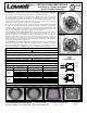
FRONT VIEW
70V-5W
70V-2W
25V-0.25W
70V-1W
25V-5W
25V-2W
25V-1W
REAR VIEW
25V-0.5W
70V-0.5W
70V-0.25W70/25V COM
8 OHM
SPKR COM
FIGURE 1
#13456
TRANSFORMER TAPS
Note: The UL dBA ratings given above are the low readings from 11 samples so they may not be as expected for one sample.
Directional Characteristics Test With Full Power Pink Noise Input Measured at 3m:
On Axis = 91.1dBA, -3dBA at 25
o
off axis, -6dBA at 55
o
degrees off axis, 84.1dBA at 90
o
off axis
Installation - Series ULD (28LO) Fire Protective Signaling Speaker
These speakers are intended to be employed in either of the following configurations:
A. For fire alarm signaling service in conjunction with a compatible Listed system control unit, the
combination of which is intended to be installed as a combination system control in accordance
with the applicable requirements of NFPA 72 and the local authorities having jurisdiction. The
amplifier, in conjunction with the tone generator located in the control unit, provides the power and
signal, either for the alarm evacuation and/or for voice communication.
B. For general (non-fire alarm) signaling service in conjunction with compatible Listed sound
recording and reproducing equipment, the combination of which is intended to be installed in
accordance with the applicable requirements of the National Electrical Code and the local
authorities having jurisdiction. The amplifier or other sound reproducing equipment provides the
power for voice communication or any other related function to the speakers.
Connection Notes: For the supervised fire system voice coil, parallel input leads are provided
on Series ULD speakers for proper utilization of the electrical supervision scheme. Connect one
pair (red and black) to the incoming line from the fire alert signal source or previous speaker.
Connect the other pair (red and black) to the outgoing line to the next speaker or end-of-line
termination device. A red jumper is connected to the 70.7V 0.5W tap when shipped from the
factory. If desired, move the red jumper to a different transformer power tap lug. See "Figure 1"
on this page for available transformer power taps.
Instruction Sheet:
IS-ULD & IS-ULS
P/N 15741
Page 1 of 2
FIRE ALARM
EQUIPMENT
28LO
SIGNALING
LISTED
U
L
R
Connection Notes: For the voice/music non-supervised voice coil, connect leads (white and
black) to the incoming line from the signal source or previous speaker. A red jumper is connected
to the 70.7V 0.5W tap when shipped from the factory. If desired, move the red jumper to a different
transformer power tap lug. See "Figure 1" this page for available transformer power taps.