www.lowrance.com Pub.
Copyright © 2006 Lowrance Electronics, Inc. All rights reserved. No part of this manual may be copied, reproduced, republished, transmitted or distributed for any purpose, without prior written consent of Lowrance. Any unauthorized commercial distribution of this manual is strictly prohibited. Lowrance® is a registered trademark of Lowrance Electronics, Inc. MapCreate™, FreedomMaps™ and NauticPath™ are trademarks of LEI. Fishing Hot Spots® is a registered trademark of Fishing Hot Spots Inc.
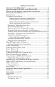
Table of Contents Section 1: Read Me First! ......................................................... 1 Specifications: LMS-520c and LMS-525cDF.......................... 3 How to use this manual: typographical conventions ................ 10 Section 2: Installation............................................................. 13 Preparations ................................................................................ 13 Transducer Installation ............................................................
Map Page ................................................................................. 51 Sonar Page ............................................................................... 52 Basic Sonar Quick Reference ............................................... 55 Sonar Operations ........................................................................ 56 Fish Symbols vs. Full Sonar Chart ........................................ 58 Section 4: Sonar Options..................................................
Map with Sonar Split Screen.................................................. 94 Sonar Simulator .......................................................................... 95 Stop Chart.................................................................................... 97 Surface Clarity ............................................................................ 98 Transparency............................................................................... 99 Upper and Lower Limits..........................
Icons ........................................................................................... 140 Create Icon on Map ............................................................... 140 Create Icon at Current Position ........................................... 140 Delete an Icon ........................................................................ 140 Navigate to an Icon ............................................................... 141 Routes ........................................................
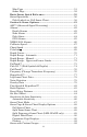
Map Datum Selection................................................................ 165 Map Detail Category Selection................................................. 166 Map Orientation........................................................................ 166 NauticPath™ USA Marine Charts........................................... 168 Nautical Chart Notes ............................................................ 168 Port Information....................................................................
Add Fuel............................................................................. 212 Fill Tank............................................................................. 212 Adding Fuel to Tank ............................................................. 212 Engine Operations................................................................. 212 Engine Select ..................................................................... 212 NMEA 2000 Alarms .....................................................
NOTICE! The storage and operation temperature range for your unit is from -20 degrees to +167 degrees Fahrenheit (-28 degrees to +75 degrees Celsius). Extended storage or operation in temperatures higher or lower than specified will damage the liquid crystal display in your unit. This type of damage is not covered by the warranty. For more information, contact the factory's Customer Service Department; phone numbers are listed on the last page of the manual.
Notes viii
Section 1: Read Me First! How this manual can get you out on the road, fast! Welcome to the exciting world of digital sonar and GPS! We know you're anxious to begin navigating and finding fish, but we have a favor to ask. Before you grab the unit and begin installing it, please give us a moment or two to explain how our manual can help you get the best performance from your compact, wide-screen, combination fish finder and mapping GPS receiver.
After you've gained some experience with your sonar, you'll want to check out Section 4, which discusses more advanced Sonar Options and Other Features. When you come to a sonar menu command on your unit’s screen, you can look it up in the manual by skimming over the table of contents, just flipping through Section 3 or scanning through the sonar options in Section 4. If you're having difficulty with your sonar, you can find an answer to the most common problems in Section 5, Sonar Troubleshooting.
Specifications: LMS-520c and LMS-525cDF General Display: ............................5.0" (12.7 cm) diagonal high contrast color Film SuperTwist LCD; programmable to viewing preference. Resolution: ......................480 pixel x 480 pixel resolution; 230,400 total pixels. Backlighting: ..................Incandescent backlit screen with multiple lighting levels; backlit keypad. Input power: ...................10 to 15 volts DC. Case size: .........................5.4" H x 6.9" W x 3.4" D (13.8 x 17.6 x 8.
Sonar sounding depth capability:............LMS-525cDF: 2,500 feet/762 meters. LMS-520c: 1,000 feet/305 meters. (Actual capability depends on transducer configuration and installation, bottom composition and water conditions. All sonar units typically read deeper in fresh water than in salt water.) Depth display: ................Continuous display. Graph recording: ...........Up to 1 GB on one MMC (or SD) card Audible alarms: ..............Deep/shallow/fish/zone. Automatic ranging: .......
Mapping memory: ...........Up to 1 GB on one MMC (or SD) card. Position updates:...........Every second. Position points: ..............1,000 waypoints; 1,000 event marker icons. Audible alarms: ..............Arrival/off-course/anchor. Graphic symbols for waypoints or event marker icons:..................63. Routes: .............................100; up to 100 waypoints per route. Plot Trails:.......................10 savable; up to 9,999 points per trail. Zoom range: ....................39 ranges; 0.
also called sonar charts or sonar graphs.) You can replay this sonar log in the unit using the Sonar Simulator function, or play it back on a personal computer using our free Sonar Viewer. The viewer is available for download from the Lowrance web site, www.lowrance.com. You can save several different sonar log files, erase 'em and record new ones, over and over again. The size of your sonar recordings is only limited by the free space available on your MMC.
icons, trails and routes. This lets you look back the way you came. Think of this data storage like the hard drive memory in a computer or a tape in a cassette tape recorder. You can save several different GPS data files, erase 'em and record new ones, over and over again. These GPS Data Files (file format *.usr) can be shared between, not only the LMS-520c and LMS-525cDF, but other Lowrance GPS units and even personal computers. Your unit has one more thing in common with a personal computer.
on page 13, so you can mount your unit and plug in the power. Or you might want to see how our text formatting makes the manual tutorials easy to skim. If that's the case, move on to "How to Use This Manual" on page 10. But, if you want to understand the current state of satellite navigation, look over this segment describing how GPS and its new companion WAAS work together to get you where you're going.
Remember, the unit must have a clear view of the satellites in order to receive their signals. Unlike radio or television signals, GPS works at very high frequencies. These signals can be easily blocked by trees, buildings, an automobile roof, even your body. Like most GPS receivers, the unit doesn’t have a compass or any other navigation aid built inside. It relies solely on the signals from the satellites to calculate a position.
of terrain! It only calculates position, it can’t know what’s between you and your destination, for example. It’s up to you to safely navigate around obstacles, no matter how you’re using this product. How to use this manual: typographical conventions Many instructions are listed as numbered steps. The keypad and arrow "keystrokes" appear as boldface type.
Keyboard The other keys perform a variety of functions. When the text refers to a key to press, the key is shown in bold, sans serif type. For example, the "Enter/Icons" key is shown as ENT and the "Menu" key is shown as MENU. Menu Commands A menu command or a menu option will appear in small capital letters, in a bold sans serif type like this: ROUTE PLANNING. These indicate that you are to select this command or option from a menu or take an action of some kind with the menu item.
Notes 12
Section 2: Installation Preparations You can install the sonar and GPS systems in some other order if you prefer, but we recommend this installation sequence: Caution: You should read over this entire installation section before drilling any holes in your vehicle or vessel! 1. Determine the approximate location for the sonar/GPS unit, so you can plan how and where to route the cables for the antenna, transducer and power.
Read these instructions carefully before attempting the installation. Determine which of the mounting positions is right for your boat. Remember, the transducer installation is the most critical part of a sonar installation. NOTE: The following installation types also call for these recommended tools and required supplies that you must provide (supplies listed here are not included): Single-frequency transom installations Tools include: two adjustable wrenches, drill, #29 (0.
at speeds faster than 35 mph. Typically, a good transom location on aluminum boats is between the ribs closest to the engine. 3. The transducer should be installed with its face pointing straight down, if possible. For shoot-thru applications: Many popular fishing boat hulls have a flat keel pad that offers a good mounting surface. On vee hulls, try to place the transducer where the deadrise is 10° or less. Deadrise less than 10° Strakes Pad Left, vee pad hull; right, vee hull.
How low should you go? For most situations, you should install your Skimmer transducer so that its centerline is level with the bottom of the boat hull. This will usually give you the best combination of smooth water flow and protection from bangs and bumps. Transom Transducer centerline Hull bottom Align transducer centerline with hull bottom. However, there are times when you may need to adjust the transducer slightly higher or lower.
However, the shoot-thru-hull installation does have its drawbacks. First, some loss of sensitivity does occur, even on the best hulls. This varies from hull to hull, even from different installations on the same hull. This is caused by differences in hull lay-up and construction. Second, the transducer angle cannot be adjusted for the best fish arches on your sonar display. (This is not an issue for flasher-style sonars.
B. Two-piece bracket: Locate the four plastic ratchets in the transducer's hardware package. Press two ratchets into the sides of the plastic bracket and two on either side of the transducer as shown in the following illustrations. Notice there are letters molded into each ratchet. Place the ratchets into the bracket with the letter "A" aligned with the alignment mark molded into the bracket.
hold it against the transom. Looking at the transducer from the side, check to see if it will adjust so that its face is parallel to the ground. If it does, then the "A" position is correct for your hull. If the transducer's face isn't parallel with the ground, remove the transducer and ratchets from the bracket. Place the ratchets into the holes in the bracket with the letter "B" aligned with the dot stamped in the bracket. Reassemble the transducer and bracket and place them against the transom.
Lock washer Bolt Nut Flat washer Flat washer Assemble transducer and bracket. 3. Assembling the transducer. A. One-piece bracket: Once you determine the correct position for the ratchets, assemble the transducer as shown in the following figure. Don't tighten the lock nut at this time. Metal washer Nut Rubber washers Metal washer Bolt Assemble transducer and bracket. B.
Transom Transom Position transducer mount on transom and mark mounting holes. Side view shown, left, and seen from above at right. 5. Attaching transducer to transom. A. One-piece bracket: Remove the transducer from the bracket and re-assemble it with the cable passing through the bracket over the bolt as shown in the following figures. For single-frequency Skimmer, route cable over bolt and through bracket. Side view shown, left, and seen from above at right.
Bottom of hull Flat-bottom hull Deep-"vee" hull Align transducer centerline with hull bottom and attach transducer to transom. Rear view of dual-frequency Skimmer shown. 6. Route the transducer cable through or over the transom to the sonar unit. Make sure to leave some slack in the cable at the transducer. If possible, route the transducer cable away from other wiring on the boat.
Trolling Motor Bracket Installation (single-frequency only) 1. Attach the optional TMB-S bracket to the transducer as shown in the following figure, using the hardware supplied with the transducer. (Note: The internal tooth washer is supplied with the TMB-S.) Internal tooth washer Bolt TMB-S bracket Nut Flat washer Attach motor mounting bracket to transducer. 2. Slide the adjustable strap supplied with the TMB-S through the slot in the transducer bracket and wrap it around the trolling motor.
Partial fish arches Transducer aimed too far back Transducer aimed too far forward Full fish arch Proper transducer angle Transducer angles and their effects on fish arches. If the arch slopes up – but not back down – then the front of the transducer is too high and needs to be lowered. If only the back half of the arch is printed, then the nose of the transducer is angled too far down and needs to be raised. NOTE: Periodically wash the transducer's face with soap and water to remove any oil film.
WARNING: Do not remove any material from your inner hull unless you know the hull's composition. Careless grinding or cutting on your hull can result in damage that could sink your boat. Contact your boat dealer or manufacturer to confirm your hull specifications. Fill with Fill with resin Inner hull Flotation material Epoxy to hull first Outer hull Epoxy the transducer to a solid portion of the hull.
To choose the proper location for shoot-thru-hull mounting, follow these testing procedures: (You may need a helper to complete these steps.) 1. Anchor the boat in about 30 feet of water. Add a little water to the sump of the boat. Plug the transducer into the sonar unit, turn it on, then hold the transducer over the side of the boat in the water. Adjust the sensitivity and range controls until a second bottom echo is seen on the display. (You'll need to turn off Auto Sensitivity, Auto Depth Range and ASP™.
4. Most people can get good results by following steps 1 through 3, so this step is optional. If you want to make an extra effort to be absolutely sure that your selected location will work under all conditions, make a test run with the boat on plane and observe the bottom signal. You'll need to figure some way to prop the transducer into position while you make your test run. (A brick or two might be sufficient to hold it in place.) 5.
WARNING: Use only the epoxy available from LEI. It has been formulated to work with these installation procedures. Other epoxy types may be too thin or may not cure to the right consistency for optimum transducer performance. 2. The epoxy consists of the epoxy itself and a hardener. Remove the two compounds from the package and place them on the paper plate. Thoroughly stir the two compounds together until the mixture has a uniform color and consistency.
First find a location on the boat's transom where the water flow is smoothest. Don't mount the sensor behind strakes or ribs. These will disturb the water flow to the speed sensor. Make sure the sensor will remain in the water when the boat is on plane. Also make sure the location doesn't interfere with the boat's trailer. Typically, the sensor is mounted about one foot to the side of the transom's centerline. Once you've determined the proper location for the unit, place the sensor on the transom.
CAUTION: If you drill a hole in the transom for the cable, make sure it is located above the waterline. After installation, be sure to seal the hole with the same marine grade above- or below-waterline sealant used for the screws. The sensor is now ready for use. Connect the sensor to the sonar socket on the back of your unit and connect the transducer to the speed sensor's socket. If you have any questions concerning the installation of the sensor, please contact your local boat dealer.
Caution: All of the wires in the power/data cable have bare ends for easier installation. The bare ends on any unused wires could cause an electrical short if left exposed. To prevent this, you should cover the individual wire ends – either by capping them with wire nuts, wrapping them with electrical tape or both. (You should cut off the bare wire before taping off the ends.) Powering Your Display Unit The display unit works from a 12-volt DC battery system.
If possible, keep the power cable away from other boat wiring, especially the engine's wires. This will provide the best isolation from electrical noise. If the cable is not long enough, splice #18 gauge wire onto it. The display power cable has three wires, white, red and black. Red is the positive (+) lead, black is negative (–) or ground. The white wire is unused by your unit and should be capped. Make sure to attach the in-line fuse holder to the red lead as close to the power source as possible.
to power even if your only NMEA 2000 device is the GPS module and it is connected to the display unit's Network socket. (However, never connect multiple power sources to a NMEA 2000 network. If you have a network that is already powered, see diagram B on page 33.) Power Diagram B To unit Display Unit Power Cable All unused Data or NMEA 2000 power wires should be capped with wire nuts and electrical tape to prevent shorts.
If you do need to power your NMEA 2000 bus, attach the NMEA 2000 Power cable to an accessory switch as indicated in power diagram A on page 32. The NMEA 2000 Power cable's red wire should be attached (with provided 3-amp fuse) to the positive (+) terminal. The NMEA 2000 Power cable's black and shield wires should both be attached to the negative (–) terminal. WARNING: The NMEA 2000 network bus is always on and constantly drawing power.
To use the module in an automobile, you may achieve good results by simply placing the external antenna on the top of the dash, at the base of the windshield. A piece of the rubber non-skid shelf liner material available in recreational vehicle supply stores will help hold the antenna in place. This may not work well if you have a cab-over design pickup truck camper or motor home. If dashboard reception is poor, simply relocate the antenna module elsewhere on the vehicle for a clearer view of the sky.
Network port on display unit Double T Connector Extension cable 120-ohm terminator 120-ohm terminator Extension cable LGC-3000 LGC-3000 and display unit as an expandable NMEA 2000 network. The diagram has a double T connector with two 120-ohm terminators — one at each end of the connector.
Com-1 To unit Orange (Receive) NMEA Transmit Shield (Ground) Ground To Other GPS Receiver Com-1 wiring to receive NMEA position information from some other GPS receiver. Yellow (Transmit) Com-1 To unit NMEA Receive Ground Shield (Ground) To Other Device Com-1 wiring to transmit NMEA position information to another NMEA-compatible device.
LMS-525CDF (rear view) Network socket Power/Data socket SP-BL optional speed sensor Ethernet socket (future enhancement) Sonar socket Double T connector 120 ohm terminator Data cable Display unit power cable 120 ohm terminator Extension cables NMEA 2000 Power cable Transducer LGC-3000 LMS-520c and LMS-525cDF cable connections.
Mounting the Unit: Bracket, In-Dash or Portable You can install your unit on the dash with the gimbal bracket. It can also be installed in the dash or mounted on a portable power supply. If you use the supplied bracket, you may be interested in the optional R-A-M® bracket mounting system. This converts the unit's gimbal bracket to a swivel mount, which can be used on the dash or overhead mounting positions. Optional R-A-M mounting system.
Front Install the gimbal bracket. Orient the bracket so the arms slope toward the front of your unit. Drill a 1-inch (25.4 mm) hole in the dash for the power, transducer and antenna cables. The best location for this hole is immediately under the gimbal bracket location. This way, the bracket can be installed so that it covers the hole, holds the cables in position and results in a neat installation.
After drilling the hole, pass the transducer connector up through the hole from under the dash, followed by antenna connector. Pass the power cable's bare-wire end down though the hole from the top. If you wish, you can fill in the hole around the cables with a good marine caulking compound. (Some marine dealers stock cable hole covers to conceal the opening.) No matter what type of installation you prefer, be sure to leave enough slack in the cables to allow tilting or swiveling the unit.
Portable Installation Like many Lowrance products, the unit is capable of portable operation by using an optional portable power pack. The power pack, a magnetequipped antenna module and an optional portable transducer, expands the uses for your sonar/GPS unit. It makes it easy to transfer your unit from a boat to a car, recreational vehicle, airplane or other vehicle without mounting a second bracket. You can use it in your own car or boat, then take it along when riding in a friend's vehicle.
Both of these solid-state flash memory devices are about the size of a postage stamp. An SD card is slightly thicker than an MMC. As this manual went to press, MMCs were available in storage capacities of 8 MB, 16 MB, 32 MB, 64 MB and 128 MB. SD cards were available with capacities of 8 MB, 16 MB, 32 MB, 64 MB, 128 MB, 256 MB and 1 GB. Additional MMC cards are available from LEI Extras; see ordering information inside the back cover of this manual.
Other Accessories Cleaning Towel A lint-free microfiber towel is included for cleaning the unit’s screen. The towel is highly effective in clearing away water spots, smudges and finger prints. Just wipe the screen with the dry towel — it's not necessary to moisten the towel with water. If the screen is badly soiled, you may use water or common window or lens cleaners. However, DO NOT use polishing compounds or any other abrasive product.
Now that you have your unit installed, move on to Section 3, Basic Sonar Operations. There, we'll present a series of step-by-step tutorials to teach you the basics of how to operate your sonar. NOTE: When you first turn the unit on, the Map Page appears. If you'd rather start learning about GPS operation first, turn over to Section 6, Basic GPS Operations. Face Cover Your unit comes with a white protective cover that snaps on and off the front of the unit.
Notes 46
Section 3: Basic Sonar Operation This section addresses the unit's most basic sonar operations. Before you turn on the sonar unit, it's a good idea to learn about the different keys, the Main Menu, the four Page screens and how they all work together. BUT, if you just can't wait to get on the water, turn to the onepage Quick Reference on page 55.
3. MENU – Press this key to show the menus and submenus, which allow you to select a command or adjust a feature. This also accesses search functions for streets, intersections, addresses and highway exits. 4. ARROW KEYS – These keys are used to navigate through the menus, make menu selections, move the map and sonar chart cursors and enter data. 5. ENT/ICONS (Enter & Icons) – This key allows you to save data, accept values or execute menu commands. It is also used to create event marker icons. 6.
You can access the Main Menu from any of the four Page screens by pressing MENU|MENU. To clear the menu screen and return to the page display, press EXIT. Main Menu. The Main Menu commands and their functions are: Screen: changes the contrast or brightness of the display screen. Sounds: enables or disables the sounds for key strokes and alarms and sets the alarm style. Transparency: adjusts the level of transparency for menus. Alarms: turns sonar and GPS alarms on or off and changes alarm thresholds.
Timers: controls the up timer, down timer and alarm clock settings. Browse MMC Files: this allows you to view the installed MMC card and the files it contains. Pages The unit has five Page displays that represent the four major operating modes. They are the Satellite Status Page, the Navigation Page, the Map Page and Sonar Page. They are accessed by pressing the PAGES key, then using ← → to select a Page. (Clear the Pages Menu by pressing EXIT.) Pages Menu showing Sonar display options.
Satellite Status Page. Navigation Page This screen has a compass rose that not only shows your direction of travel, but also the direction to a recalled waypoint. To get to the Navigation Page: Press PAGES| → or ← to NAVIGATION|EXIT. This page represents a GPS function, but also has a navigation with sonar option, which will keep you updated on what is under your boat as well as where you’re going. Navigation page with Sonar (left). Navigation Page with digital data (right).
Map Pages, showing position on Bull Shoals Lake, Arkansas. The full map option (left). Map with sonar option (right). Map Page is also the default screen that appears when you turn on the unit. To get to the Map Page from another page: Press PAGES| → or ← to MAP|EXIT. You can display a split screen showing both the Map and Sonar pages at the same time. This feature is discussed in Sec. 4, Sonar Options & Other Features.
Pages Menu (left) showing sonar chart display option commands. Sonar Page in full sonar chart display mode (right). Split Zoom page (left) and Split Frequency page (right). Digital Data page (left) and Flasher page (right).
Sonar Page Menu. Digital data overlay (depth & temperature) Surface signal Surface clutter Depth scale In FasTrack, fish arches show as horizontal bars. Fish arches Zoom bar Structure Bottom signal FasTrack bar graph Sonar Page showing full sonar chart mode. You can customize how the Sonar Page displays its pictures and other data in many ways. We'll discuss all of those features and options in Sec.
Basic Sonar Quick Reference 1. Depress the PWR key to turn on the unit. 2. Opening screen displays Map Page. Rotate through the four main Page screens (Map Page, Satellite Status Page, Navigation Page, Sonar Page) by pressing PAGES|← or → to select Page Name|EXIT. Switch Pages to display Sonar Page. 3. If GPS data is desired, wait while unit locates satellites and calculates current position. When the unit acquires position, a tone sounds and a position acquired message appears. 4.
Sonar Operations As you can see from the quick reference on the previous page, basic operation is pretty easy, right out of the box. If you are a sonar novice, try operating the unit with the factory defaults until you get a feel for how it's working. As you're learning the basics, there is one setting you might want to tinker with from time to time — Sensitivity. Sensitivity controls the unit's ability to pick up echoes. If you want to see more detail, try increasing the sensitivity, a little at a time.
You can change the sensitivity level whether you are in Auto Sensitivity mode or Manual Sensitivity mode. The adjustment method works the same in both modes, but it gives you slightly different results. Adjusting sensitivity in Auto Sensitivity Mode is similar to manually adjusting a car's speed with the accelerator pedal while cruise control is on. You can tell the car to run faster, but when you let off the gas the cruise control automatically keeps you from running slower than the minimum speed setting.
NOTE: If you want to change the sensitivity in Manual Mode, first turn off Auto Sensitivity: from the Sonar Page, press MENU|↓ to AUTO SENSITIVITY|ENT|↑ to SENSITIVITY|ENT. Press ↓ or ↑ to pick a different sensitivity setting. When it's set at the desired level, press EXIT. Important Tip: While you are experimenting and learning, it's possible to scramble the settings so that the sonar picture disappears from your screen.
Other Free Training Aids The sonar options section discusses Fish I.D., fish alarms and other features in greater detail. If you or a friend has Internet access, you can also learn more about interpreting what you see on your sonar screen. Visit our web site, www.lowrance.com. Be sure to check out the free Sonar Tutorial, which includes animated illustrations and more pictures of actual sonar returns, all described in detail.
Free training emulator is available for your unit on our web site. The emulator works exactly like your real sonar/GPS unit. Using the Sonar Simulator and GPS Simulator features, it allows you to play back sonar logs, run GPS routes and trails and create real waypoints you can use in the field! You can even take snapshots of the Sonar Chart and print them or e-mail them to friends.
Section 4: Sonar Options ASP™ (Advanced Signal Processing) The ASP™ feature is a noise rejection system built into the sonar unit that constantly evaluates the effects of boat speed, water conditions and interference. This automatic feature gives you the best display possible under most conditions. The ASP feature is an effective tool in combating noise. In sonar terms, noise is any undesired signal.
Alarms This unit has three different types of sonar alarms. The first is the Fish Alarm. It sounds when the Fish I.D.™ feature determines that an echo is a fish. Another alarm is the Zone Alarm, which consists of a bar on the side of the screen. Any echo on the chart that appears inside this bar triggers this alarm. The last alarm is the Depth Alarm, which has both a Shallow and a Deep setting. Only the bottom signal will trigger this alarm.
3. Press ↑ or ↓ to change the first number, then press → to move the cursor to the next number and repeat until the depth is correct, then press ENT. 4. Press ← to SHALLOW ALARM ENABLED|ENT|EXIT|EXIT|EXIT. 5. To turn off the alarm, press MENU|MENU|↓ to ALARMS|ENT|↓ to SONAR ALARMS|ENT|ENT|EXIT|EXIT|EXIT. To switch to a different depth setting, open the Sonar Alarms menu and repeat the instructions in step 3 above. To adjust and turn on the deep alarm: 1.
Sonar Alarms menu with Adjust Zone command selected (left). Adjust Zone Alarm selection box with Upper selected (right). 3. To set the upper boundary for the Zone Alarm, use ← or→ to select UPPER, then press ↑ or ↓ to move the top of the bar to the desired depth. 4. To set the lower boundary for the Zone Alarm, use ← or→ to select LOWER, then press ↑ or ↓ to move the bottom of the bar to the desired depth. 5. Press EXIT|← to ZONE ALARM ENABLED|ENT|EXIT|EXIT|EXIT.
Sonar Alarms menu with Fish Alarm selected. The check box to the left is blank, indicating the alarm is turned off. To turn on fish alarm: 1. Press MENU|MENU|↓ to ALARMS|ENT|↓ to SONAR ALARMS|ENT. 2. Press ↓ to FISH ALARM|ENT|EXIT|EXIT|EXIT. 3. To turn off the alarm, press MENU|MENU|↓ to ALARMS|ENT|↓ to SONAR ALARMS|ENT|↓ to FISH ALARM|ENT|EXIT|EXIT|EXIT. GPS Alarms You can set an arrival alarm to flash a warning message and sound a tone when you cross a preset distance from a waypoint.
The anchor alarm is triggered when you drift outside of a preset radius. Using the .1 mile as an example, if you're anchored and the boat moves more than .1 miles, a tone will sound and a message will appear. 1. To set an alarm, press MENU|MENU|↓ to ALARMS|ENT|ENT. 2. Use ↓ ↑ to select the desired category, then press ENT to turn on (check) or turn off (uncheck) the desired Alarm Enabled box. 3.
NMEA 2000 Alarms highlighted on Alarms menu (left). NMEA 2000 Alarms menu (center). Alarm Status page (right). 3. To enable the Empty Alarm, highlight the EMPTY ALARM Enabled box and press ENT to turn on (check) the alarm. Press → to the Percent box and press ENT. Use the ↑ ↓ keys to select the first number, then press → to move to the next number. When the desired percentage has been entered, press ENT. Tip You do not have to set both the Full and Empty alarms.
A good way to gauge your speed sensor's performance is to compare its reading with the ground speed measured by your unit's GPS functions. When you make a run to compare GPS ground speed to speed sensor speed, perform your test in relatively calm water free of current, if possible. (Unless, of course, you are taking the speed of current into consideration when making your calculation.) After you have a correction figure, here's how to enter it: 1.
If you do experiment with chart speed, remember to reset it to maximum when you resume trolling or moving across the water at higher speed. To change chart speed: 1. From the Sonar Page, press MENU|↓ to CHART SPEED|ENT. 2. The Chart Speed Control Bar appears. Press ↓ to decrease chart speed; press ↑ to increase chart speed. 3. When it's set at the desired level, press EXIT. Colorline™ Colorline lets you distinguish between strong and weak echoes.
To adjust Colorline level: 1. From the Sonar Page, press MENU|↓ to COLORLINE|ENT. 2. The ColorLine Control Bar appears. Press ↓ to decrease ColorLine; press ↑ to increase ColorLine. 3. When it's set at the desired level, press EXIT. Wider ColorLine Thin or no ColorLine A small amount of Colorline (left) is indicative of a soft bottom. A wider patch of Colorline indicates a harder bottom (right). Depth Cursor The depth cursor consists of a horizontal line with a digital depth box on the right side.
The cursor can be moved to any location on the screen, letting you pinpoint the depth of a target. 1. From the Sonar Page, press MENU|↓ to DEPTH CURSOR|ENT. 2. The depth cursor appears. Press ↓ to lower the cursor line; press ↑ to raise the cursor line. 3. To clear the depth cursor, press EXIT. Depth Range - Automatic When turned on for the first time, the bottom signal is automatically placed in the lower half of the screen. This is called Auto Ranging and is part of the automatic function.
3. Press ↓ or ↑ to select a different depth range. A horizontal blue bar highlights the selected range. 4. When the new range is selected, press EXIT to clear the menu. Repeat these steps to turn on Auto Depth Range. NOTE: The sonar's depth capability depends on the water, bottom conditions, transducer installation and other factors. Depth Range - Upper and Lower Limits Virtually any segment of the water column can be displayed by using the upper and lower limit feature.
3. To set the lower limit, press ↓ to LOWER LIMIT|ENT. Press ↑ ↓ to change the first number, then press → to move the cursor to the next number and repeat until the depth is correct, then press EXIT repeatedly. Fish arches Area "zoomed" Normal display, in auto depth range mode (left). Display "zoomed" with Upper and Lower Limits focusing on the portion of the water column from 20 feet to 40 feet deep (right).
Surface clutter Fish arches Structure In FasTrack, fish arches show as horizontal bars. Bottom signal Sonar Page showing FasTrack. FasTrack bar graph Fish I.D.™ (Fish Symbols & Depths) The Fish I.D. feature identifies targets that meet certain conditions as fish. The microcomputer analyzes all echoes and eliminates surface clutter, thermoclines, and other signals that are undesirable. In most instances, remaining targets are fish. The Fish I.D.
Sonar Features menu with Fish I.D. Symbols selected on dualfrequency menu (left); single-frequency menu (right). When the check box to the left is checked, the feature is on. Fig. 1 A Fig. 1 B Many fish arches visible Fewer fish symbols visible Fig. 2 A Fig. 2 B Fish arches above structure No fish shown FasTrack graph confirms fish Figures 1A and 2A show Sonar Page in normal chart mode (left). Figures 1B and 2B (right) show the same underwater scene with Fish I.D. turned on.
To turn the Fish I.D. feature on: 1. From the Sonar Page, press MENU|↓ to SONAR FEATURES|ENT. 2. Press → to FISH SYMBOLS|ENT|EXIT|EXIT. To turn off Fish I.D., repeat the instructions in step 2. FishTrack™ The FishTrack feature shows the depth of a fish symbol when it appears on the display. This lets you accurately gauge the depth of targets. This feature is available only when the Fish I.D. feature is on. The default setting for FishTrack is off.
The default frequency is 200 kHz, which is best for use in shallow water (about 300 feet or less). This frequency is the best choice for about 80 percent of the fresh and salt water sport fishing applications. When you get into very deep salt water, 300 to 500 feet or deeper, the 50 kHz frequency is the best choice. The 200 kHz transducer will give you better detail and definition, but less depth penetration.
Log Sonar Chart Data If you have an MMC installed in the unit, the sonar data shown on the screen can be saved to the MMC. This can be played back at any time (to play a recorded sonar chart log, see the entry in this section for Sonar Simulator). If you have a personal computer and Internet access, visit our web site, www.lowrance.com, and download the free Sonar Viewer and the emulator for your unit. These programs will allow you to replay sonar logs on your personal computer.
Noise Rejection See the entry on Advanced Signal Processing in this section. Overlay Data On any Page display except Satellite Status, you can "float" or overlay additional GPS or navigation data on the screen with the Overlay Data command. For example, if you left your watch at home, you could display the local time on top of the map. Or, if you wanted to see details about your route and trip, you could show your bearing, course, average speed and trip distance.
Data Viewer menu (left). Sonar Data category expanded (right). 3. Expand any categories that might contain data you want to display. Then press ↓ or ↑ to select a data option. 4. With the data option highlighted, press ENT to check it (turn on) and uncheck it (turn off). As you turn it on, the data will appear on top of the screen. Every Page display has a maximum number of items you can show using the Overlay Data command. 5.
To remove overlaid data: 1. While on the Page that shows the item or items you want to remove, press MENU|↓ to OVERLAY DATA|ENT. 2. You'll see a list of the overlay data currently displayed. Select the item you want to remove from your display and press ENT|ENT to remove the data. To remove another item, select the item and press ENT|ENT. 3. When you have finished removing all the items you want from the screen, press EXIT to return to the page display.
screen, and Overlay Data changes only the information floating on the screen without a box. See Customize Page Displays, on page 90, for information on customizing data boxes. To change displayed data font size: 1. From the Map or Sonar page, press MENU|↓ to OVERLAY DATA|ENT. 2. Press ↓ or ↑ to select Data Type, then use ← → to scroll through the five overlay options: Off, Small, Medium, Large and Enormous. 3. Select the desired setting. The selected data type will be displayed in the new size.
Sonar Menu with Ping Speed selected (left). Ping Speed Control Bar set to its default setting (right). To change Ping Speed: 1. From the Sonar Page, press MENU|↓ to PING SPEED|ENT. 2. The Ping Speed Control Bar appears. Press ↑ to increase ping speed; press ↓ to decrease speed. When it's set at the desired level, press EXIT. To adjust Sensitivity: 1. From the Sonar Page, press MENU|ENT. 2. The Sensitivity Control Bar appears. Press ↓ to decrease sensitivity; press ↑ to increase sensitivity.
3. All the menus are cleared and the unit reverts to the Map Page at the 4000 mile zoom range, just as if you had turned it on for the first time. All options have been returned to the factory settings. System Setup menu with Reset Options selected (left). The Reset Options dialog box, with "Yes" selected (right). NOTE: Reset Options does not erase any waypoints, routes, plot trails, or sonar logs.
The Keel Offset feature eliminates the need for the navigator to mentally calculate how much water is under his keel. Keel Offset lets you calibrate the digital depth, chart depth scale, chart cursor depth and fish symbol depth displayed on the screen. To calibrate the depth indicators, first measure the distance from the face of the transducer to the lowest part of the boat. In this example, we will use 3.5 feet. This will entered as a negative 3.
High sensitivity levels let you see this detail, but it can also clutter the screen with many undesired signals. Typically, the best sensitivity level shows a good solid bottom signal with Colorline and some surface clutter. Automatic Sensitivity The default sensitivity mode is automatic. The unit bases the sensitivity level on water depth and conditions. When the unit is in the automatic mode, sensitivity is automatically adjusted to keep a solid bottom signal displayed, plus a little more power.
Sonar Menu with Sensitivity selected (left). The Sensitivity Control Bar (right). To adjust sensitivity in manual mode: 1. First, turn off Auto Sensitivity: from the Sonar Page, press MENU|↓ to AUTO SENSITIVITY|ENT. 2. Press ↑ to SENSITIVITY|ENT and the Sensitivity Control Bar appears. Press ↓ or ↑ to pick a different sensitivity setting. When it's set at the desired level, press EXIT. To turn Auto Sensitivity back on: From the Sonar Page, press MENU|↓ to AUTO SENSITIVITY|ENT|EXIT.
To change the chart mode color scheme:+ 1. From the Sonar Page, press MENU|↓ to SONAR FEATURES|ENT. 2. Press ↓ to SONAR CHART MODE|ENT. 3. Press ↓ or ↑ to Mode Name|ENT. 4. Press EXIT|EXIT to return to the Sonar Page. Sonar Page & Sonar Chart Display Options The Pages Menu offers five chart display options for dual-frequency models and four options for single-frequency models. To access them, press PAGES|← or→ to SONAR|↓ to Option Name|EXIT. Pages Menu showing sonar chart display options.
Full Sonar Chart. The Overlay Data (depth and water temperature) are both set to the small text size. Split Zoom Sonar Chart A split chart shows the underwater world from the surface to the bottom on the right side of the screen. The left side shows an enlarged version of the right side. The zoom range shows in the bottom left corner. Split Zoom Sonar Chart. The left window is zoomed 2X in the first image (left). The left window is zoomed 4X in the second image (right).
3. The Sensitivity Control Bar appears. Press ↓ to decrease sensitivity; press ↑ to increase sensitivity. When it's set at the desired level, press EXIT. (When you reach the maximum or minimum limit, a tone sounds.) The Split Frequency Sonar Chart page allows you to adjust sensitivity separately for each window. Digital Data/Chart This mode shows the chart on the right side of the screen.
Calculator, Time, Sonar Data and Miscellaneous Data. You can select items from any of these categories for display in any data box — the category divisions are only there to help you sort through the information. To change the information displayed in a data box: 1. On the Page display you wish to change, press MENU|↓ to CUSTOMIZE|ENT. A data box name flashes, indicating it is selected. 2. Press ENT to change the box or hit ↑, ↓, → or ← to select another box, then press ENT.
Flasher The Flasher sonar page option represents a flasher style sonar combined with a scrolling chart. A circular dial shows all returning echoes at a high screen refresh rate. It uses the Colorline feature to show weaker targets as lighter colors. The bottom depth is also shown as a black bar across the outer circle. You can adjust the size of the chart and the flasher windows by using the Resize Window command, which is described in Sec. 6.
To customize digital gauge display: 1. Press PAGES, highlight SONAR WITH CUSTOM GAUGES and press ENT. 2. Press MENU, select OVERLAY DATA and press ENT. The Overlay Data shown menu will appear. 3. Highlight (PRESS ENT TO ADD…) and press ENT to open the Data Viewer menu with three expandable data categories: Time, Sonar Data and Sensor Data. 4. Highlight the desired data category and press ENT, which will expand the list, revealing several subcategories with checkboxes next to them. 5.
To resize Sonar and Custom Gauge windows: 1. From the Sonar with Custom Gauges page, press MENU, select RESIZE WINDOW and press ENT. 2. Use ← → to increase or decrease the size of each window. Press EXIT. When the Resize Windows command is active, two arrows will appear between the two windows. Map with Sonar Split Screen There is a page mode that splits the screen in half, with the map on the left and the sonar on the right. This screen option can be found on the Pages Menu under the Map Page category.
Sonar Simulator This unit has a built-in simulator that lets you run it as if you were on the water. All sonar features and functions are useable. When in simulator mode, you will see the chart file name in the Sonar Page title bar and a play symbol will flash on and off at the right end of the title bar. To use the simulator: 1. From the Sonar Page, press MENU|MENU|↓ to SYSTEM SETUP|ENT|↓ to SIMULATORS|ENT. System Setup menu with Simulators selected (left).
"Play" symbol flashing Title bar with chart file name Sonar Page, playing a recorded sonar chart in Sonar Simulator mode. Tip: The Sonar Simulator can use sonar charts that you or a friend have recorded (logged) on a MMC card. (To see how, read the entry in this section on Log Sonar Chart Data.) To play back your own sonar chart, make sure the MMC containing the chart is installed, then: 1. Press MENU|MENU|↓ to SONAR SETUP|ENT|↓ to SONAR SIMULATOR|ENT. 2. Press ↓ to CHART USED|ENT. 3.
Select Browse MMC Files from the Main Menu. NOTE: If you turn on your unit before attaching a transducer, it may enter a demo mode. The words "demo mode" flash on the bottom of the screen and a sonar chart plays much like the simulator. Unlike the simulator, the demo mode is for demonstration only, and will automatically stop as soon as you turn on the unit with a transducer attached. The simulator will continue to function normally.
Surface Clarity The markings extending downward from the zero line on the chart are called "surface clutter." These markings are caused by wave action, boat wakes, temperature inversion and more. The surface clarity control reduces or eliminates surface clutter signals from the display. It does this by changing the sensitivity of the receiver, decreasing it near the surface and gradually increasing it as the depth increases. There are three levels of surface clarity available: low, medium, or high.
Surface clutter In the illustration at left, Surface Clarity is turned off. The right view shows Surface Clarity set at High. Transparency Use the transparency menu to adjust the transparency of menu windows. A high transparency allows you to continue monitoring the screen's display while adjusting feature settings, though the text of the menus may fade until it is unreadable. A low transparency will usually make menu text easier to read, at the cost of watching your display.
Upper and Lower Limits See the entry in this section for Depth Range - Upper and Lower Limits. Zoom & Zoom Bar "Zooming" the display is a common, fast and easy method used to enlarge small detail, fish signals and the bottom with its associated structure. This unit lets you zoom the display quickly and easily by pressing the Zoom In key, ZIN. Pressing ZIN once doubles the size (2X) of all echoes on the screen. Pressing it again quadruples the size of the echoes (4X).
Section 5: Sonar Troubleshooting If your unit is not working, or if you need technical help, please use the following troubleshooting section before contacting the customer service department. It may save you the trouble of returning your unit for repair. For contact information, refer to the last page, just inside the back cover of this manual. Unit won't turn on 1. Check the power cable's connection at the unit. Also check the wiring. 2. Make sure the power cable is wired properly.
3. The water may be deeper than the sonar's ability to find the bottom. If the sonar can't find the bottom signal while it's in the automatic mode, the digital sonar display will flash continuously. It may change the range to limits far greater than the water you are in. If this happens, place the unit in the manual mode, then change the range to a realistic one, (for example, 0-100 feet) and increase the sensitivity. As you move into shallower water, a bottom signal should appear. 4.
In severe cases, it can completely cover the screen with black dots, or cause the unit to operate erratically, or not at all. To eliminate or minimize the effects of electrical noise, first try to determine the cause. With the boat at rest in the water, the first thing you should do is turn all electrical equipment on the boat off. Make sure the engine is also off. Turn your sonar on, then turn off Noise Reject [also known as the ASP feature (Advanced Signal Processing)].
Notes 104
Section 6: Basic GPS Operations This section addresses the unit's most basic GPS operations. Before you turn on the unit and find where you are, it's a good idea to learn about the different keys, the four Page screens and how they all work together. BUT, if you just can't wait to get outside, turn to the one-page Quick Reference on page 121.
3. MENU – Press this key to show the menus and submenus, which allow you to select a command or adjust a feature. This also accesses search functions for streets, intersections, addresses and highway exits. 4. ARROW KEYS – These keys are used to navigate through the menus, make menu selections, move the map cursor and sonar chart cursor and enter data. 5. ENT/ICONS (Enter & Icons) – This key allows you to save data, accept values or execute menu commands. It is also used to create event marker icons. 6.
You can access the Main Menu from any of the four Page screens by pressing MENU|MENU. To clear the menu screen and return to the page display, press EXIT. Main Menu. The Main Menu commands and their functions are: Screen: changes the contrast or brightness of the display screen. Sounds: enables or disables the sounds for key strokes and alarms and sets the alarm style. Transparency: adjusts the level of transparency for menus. Alarms: turns GPS or sonar alarms on or off and changes alarm thresholds.
Timers: controls the up timer, down timer and alarm clock settings. Browse MMC Files: this allows you to view the installed MMC card and the files it contains. Pages The unit has four Page displays that represent the five major operating modes. They are the Satellite Status Page, the Navigation Page, Map Page and the Sonar Page. They are accessed by pressing the PAGES key, then using → or ← to select a Page. (Clear the Pages menu by pressing EXIT.) Pages Menu showing Map page options.
Satellite Status Page (left). Custom Gauges (right). This screen will show a graphical view of the satellites that are in view. Each satellite is shown on the circular chart relative to your position. The point in the center of the chart is directly overhead. The small inner ring represents 45° above the horizon and the large ring represents the horizon. North is at the top of the screen.
5. Select the desired subcategory and press ENT, which will place a checkmark in the checkbox, showing the selected data is set for display. 6. If you want to display other data types, repeat Steps 4 and 5. Press EXIT repeatedly to get back to the Custom Gauges page. The data you selected will now be displayed on the screen. To change Overlay data size: 1. From the Custom Gauges page, press MENU SELECT OVERLAY DATA and press ENT. The Overlay Data Shown menu will appear. 2.
Track or compass heading indicator, showing direction of travel Navigation information displays in customizable data boxes Compass rose Present position arrow Trail line The Navigation with Digital Data Page recording a trail, while traveling southwest. Page looks like this when the unit is not navigating to a waypoint, following a route, or backtracking a trail. Navigation with Sonar page.
It's the speed that you're making toward the waypoint. For instructions, see the Customize Page Displays entry in Sec. 8.) Track is the heading, or the current direction you are actually traveling. Bearing is the direction of a line-of-sight from your present position to the destination. No matter what direction you are steering, the Bearing window shows the compass direction straight to the destination from your location at the moment. Distance shows how far it is to the waypoint you're navigating toward.
A circular symbol showing your destination (waypoint) appears on the screen as you approach the waypoint, as shown on the screen in the preceding figure. Travel Time is the time that it will take to reach your destination at your present closing speed. (You can also customize the time data box to show Arrival Time instead. Arrival Time is the local time it will be when you arrive at the destination, based upon your present closing speed and track.
Map Page opening screen (left). Set to 100-mile zoom (center) and 10mile zoom (right). Over Zoomed means you have reached the detail limits in an area covered only by the basic background map. Zooming in closer will reveal no more map detail because a high-detail custom map has not been loaded on the MMC for this area. If you're using only the factory-loaded background map, the maximum zoom range for showing additional map detail is 20 miles.
and some major city streets. Also included are Interstate, U.S. and state highways, large- and medium-sized lakes and streams and more than 60,000 navigation aids with 10,000 wrecks and obstructions in U.S. coastal and Great Lakes waters. New for 2007 are more than 3,000 enhanced lake maps that show better defined shorelines, depth contours and other underwater features. MapCreate custom maps include massive amounts of information not found in the background map.
Tip: In some urban areas, businesses are so close to one another that their POI icons crowd each other on the screen. You can reduce screen clutter and make streets and other map features easier to see by simply turning off the display of POIs you're not watching for. (To see how, check the text on Map Detail Category Selection, page 166. It shows how to use the Map Categories Drawn menu to turn individual POI displays off and on.
Pages Menu with Two Map option selected (left). The windows are in a horizontal position. Map Page with two vertical windows (right). Resize Window is another feature for pages that have two major windows. You can change the horizontal size of the windows to suit your viewing preference. 1. From any two-window display, press MENU|↓ to RESIZE WINDOW|ENT. 2. Four flashing arrows appear along the centerline dividing the two windows.
Map with Sonar highlighted on Pages menu (left). Resize Windows selected on Map with Sonar menu (center). Dual arrows are shown as windows are resized (right). Map with Custom Gauges The Map with Custom Gauges page has a split screen with a map on the right side and digital gauge information on the left side. The two windows can be resized to make one side bigger than the other or may be set up to split the screen evenly. Map with Custom Gauges highlighted on Pages menu (left).
4. Highlight the desired data category and press ENT, which will expand the list, revealing several subcategories with checkboxes next to them. 5. Select the desired subcategory and press ENT, which will place a checkmark in the checkbox, showing the selected data is set for display. 6. If you want to display other data types, repeat Steps 4 and 5. Press EXIT repeatedly to get back to the Map with Custom Gauges page.
Radar Page (left) with Radar menu display (right). To access Radar Page: 1. Press PAGES, highlight the RADAR tab and press ENT. 2. Press MENU to open the Radar menu. Press EXIT to return to the radar display. The following page contains a 12-step quick reference for the most basic GPS operations.
Basic GPS Quick Reference Start outdoors, with a clear view of the open sky. As you practice, try navigating to a location at least a few blocks away. Navigation in too small an area will constantly trigger arrival alarms. 1. Depress the PWR key to turn on the unit. 2. Opening screen displays map of North America at the 4,000 mile zoom range. Rotate through the four main Page screens (Map Page, Satellite Status Page, Navigation Page and Sonar Page) by pressing PAGES|← or → to select Page Name|EXIT.
Find Your Current Position Finding your current position is as simple as turning on the unit. Without obstruction from dense foliage, terrain or structures, the unit automatically searches for satellites and calculates its position in approximately one minute or less. If for some reason satellite acquisition takes longer, you may be inside a structure or vehicle or in terrain that is blocking signal reception.
Cursor line Cursor line Selected airport POI pop-up data box Distance measured by cursor The selected airport to the northwest is 4.2 miles away. Selecting Any Map Item with the Cursor 1. Use the zoom keys and the arrow keys to move around the map and find the item you wish to select. 2. Use the arrow keys and center the cursor crosshairs on the desired object. On most items, a pop-up box will give the name of the selected item.
After the unit has acquired a position: 1. Press WPT|↓ to POI-RESTAURANTS. 2. You could search the entire restaurant category, but in this example we will narrow our search. Press → to SUBCATEGORY column|↓ to FAST FOOD CHAINS|ENT|↓ to NEAREST|ENT. 3. The unit says it is calculating, then a list of restaurants appears, with the closest highlighted at the top of the list. The restaurant farthest from you is at the bottom of the list. Find Waypoint Menu (left). Category Selection menu (center).
6. The unit's map appears, with the cursor crosshairss highlighting the restaurant's POI symbol. A pop-up data box shows the POI's name, distance and bearing. A data box at the bottom of the screen continues to display the location's latitude and longitude. Map screen showing Finding Waypoint, the result of a restaurant search. 7. To clear the search and return to the last page displayed, press EXIT repeatedly.
Create Waypoint at Current Position While you are traveling, press WPT|WPT. The waypoint is saved and automatically given a name with a sequential number, such as "waypoint 003." The waypoint symbol and number appear on the map. Step 1. Step 2. Step 3. Step 4. Sequence for setting a waypoint. Step 1: while traveling, press WPT twice to call up the Find Waypoint screen (seen in Step 2) and set a waypoint. Step 3: a message says the waypoint has been saved.
Create Waypoint on Map 1. Use the arrow keys to move the cursor crosshairs to the place where you want to make a waypoint. 2. Press WPT|WPT. The waypoint is saved and automatically given a name with a sequential number, like "waypoint 001." The waypoint symbol and number appear on the map. Navigate To a Waypoint You can select any waypoint visible on the Map Page with the cursor, then use the Navigate to Cursor command (we'll describe how later in this section.
Of course, the first thing to do is remain calm and then use all standard safety procedures to rescue the person. This unit has a man overboard feature that shows navigation data to the location where the feature was activated. To activate it, press the ZOUT and ZIN keys at the same time. Your position at the time these keys are pressed is used as the man overboard position. Caution: Saving a new "Man Overboard" waypoint will overwrite the previous "Man Overboard" waypoint.
1. Use the cursor (controlled by the arrow keys) with the zoom in and zoom out keys to maneuver around the map until you find a location you want to go to. 2. Center the cursor over the location to select it. See the example in the following figure. (Many map items such as waypoints, Points of Interest, towns, etc. can be "selected," and appear "highlighted" with a pop-up box.
To stop navigating to the cursor, use the Cancel Navigation command: press MENU|MENU|↓ to CANCEL NAVIGATION|ENT|← to YES|ENT. The unit stops showing navigation information. Navigate to a Point of Interest For POIs that are in view on the map, you can easily use the Navigate to Cursor command above; just use the cursor to select the POI. The other method involves searching for POIs with the Find Waypoint command, launched with the WPT key. (See the searching example earlier in this section, or turn to Sec.
By default, the trail flashes once a second, making it easier to see against the background map. With the default auto setting, this unit creates a trail by placing a dot (trail point) on the screen every time you change directions. (The methods used for creating a trail and the trail update rate can both be adjusted or even turned off. See Sec. 8 for Trail Options.
New trail, named "Trail 2," is created when Trail 1 is made inactive. Any new travel will be recorded in this trail, which is active and visible. Trails do not need to be visible in order to be active. You can save and recall up to 10 different plot trails, which can be copied to your MMC for archiving or for transfer to your MapCreate software. Tip: Another quick way to stop recording one trail and begin a new one is to use the New Trail command: Press MENU|MENU|↓ to MY TRAILS|ENT|ENT.
To turn on trail display: 1. Press MENU|MENU|↓ to MY TRAILS|ENT. 2. Press ↓ to enter the Saved Trail list, then use ↑ ↓ to select the desired Trail Name|ENT. 3. Press ↓ to ACTIVE|→ to VISIBLE|ENT. To return to the previous page, press EXIT repeatedly. Navigating Trails There are three methods for following a trail: visual trailing, navigating a trail (forward) and backtracking a trail (backward). Try each method to see which you prefer. Visual trailing is the simplest method.
3. Press → to DELETE TRAIL|↓ to NAVIGATE|ENT. 4. Press ↓ to NAVIGATE|ENT. The unit begins showing navigation information along the trail. NOTE: If you are already located at or near the beginning of your trail, the arrival alarm will go off as soon as you hit Enter. Press EXIT to clear the alarm and proceed. 5. Now, begin navigating with your unit. 6. When you reach your destination, be sure to cancel your navigation: press MENU|MENU|↓ to CANCEL NAVIGATION|ENT. The unit asks if you're sure; press ←|ENT.
North Ï Present position arrow Trail point Trail dotted line Navigate trail, map views: Driver is northbound heading straight toward trail point 6 (left). Northbound driver has reached point 6 and has turned west to follow trail (right).
NOTE If you are already located at or near the end of your trail, the arrival alarm will go off as soon as you hit ENT. Press EXIT to clear the alarm and proceed. 5. Now, begin navigating with your unit. 6. When you reach your destination, be sure to cancel your navigation: press MENU|MENU|↓ to CANCEL NAVIGATION|ENT. The unit asks if you're sure; press ←|ENT. Transfer Custom Maps and GPS Data Files Custom Maps: Custom maps work only from the MMC card or SD card.
Transfer My Data highlighted (left). When transferring data (right) you will have the option of transferring the unit's data to a MMC card or loading the data on the MMC card into the unit. 3. Saving to MMC: To accept the default name "Data" for the GPS Data File, press ↓ to SAVE DATA|ENT. If you want to rename the file (as shown in the following figures), press ENT to activate the selection box.
Figure 1. Figure 2. Figure 3. Figure 4. These figures show the menu sequence for loading a GPS Data File from an MMC into the unit's memory. Cancel Navigation You can turn off any of the navigation commands after you reach your destination or at any other time by using the Cancel Navigation command. Press MENU|MENU|↓ to CANCEL NAVIGATION|ENT|← to YES|ENT.
Section 7: Advanced GPS Operations Find Distance from different Locations 1. While on the Map Page press: MENU|↓ to FIND DISTANCE|ENT. 2. Center your cursor over the position you want to find the distance to. A rubber band line appears, connecting your current position to the cursor's location. The distance along that line will appear in a pop-up box. The box also shows the bearing to the point you're measuring to. 3. Press EXIT to return to regular operation. Distance from Dallas to Little Rock is 292.
Icons Icons are graphic symbols used to mark some location, personal point of interest or event. They can be placed on the map screen, saved and recalled later for navigation purposes. These are sometimes referred to as event marker icons. This unit has 42 different symbols you can pick from when creating an icon. Icons are similar to waypoints, but they do not store as much information (like names) as waypoints do. You can't use a menu to navigate to icons as you can with waypoints.
1. Press MENU|↓ to DELETE MY ICONS|ENT. 2. Press ↓ to DELETE ALL ICONS, DELETE BY SYMBOL, or DELETE FROM MAP and press ENT. Delete icons menu. The Delete All Icons command will ask if you are sure. Press ← to YES|ENT. All icons will be deleted from the map. The Delete by Symbol command will launch the Select Symbol menu. Press ← or ↑ or → or ↓ to select the icon symbol to delete, then press ENT. A message appears saying all icons with the selected symbol have been deleted.
The course from one waypoint to the next is a leg. Routes are composed of one or more legs. The legs of all GPS routes are based on straight lines between waypoints. A route provides the automatic capability to navigate through several waypoints without having to reprogram the unit after arriving at each waypoint.
1. From the NAVIGATION PAGE, press MENU|ENT or from the MAP PAGE, press MENU|MENU|↓ to ROUTE PLANNING|ENT|ENT. 2. Press ↓ to (END OF ROUTE)|ENT|↓ to ADD FROM MAP|ENT. The Map Page appears with the cursor showing. Edit Route menu (left). Edit Route Waypoints menu (right) with Add From Map command selected. 3. Use the Zoom keys and arrow keys to move the map and cursor until the cursor is centered on the spot where you want your route to begin.
4. Set the first route waypoint: press ENT. In this example, we started our route at the intersection of 11th Street and 145th E. Ave. The route ends at a public hunting area next to a river. (Our route creation example is illustrated in the following figures.) 4. 5. 6. Route creation sequence, continued: Fig. 4. Point (3) set at on-ramp turn. Fig. 5. Waypoint (4) set at highway exit to frontage road leading to river. Waypoint (5) ends the route at a tree stand in the hunting area. Fig. 6.
Edit a Route Name 1. From the NAVIGATION PAGE, press MENU|ENT or from the MAP PAGE press MENU|MENU|↓ to ROUTE PLANNING|ENT. 2. Press ↓ to route name|ENT|ENT. 3. Press ↑ or ↓ to change the first character, then press → to move the cursor to the next character and repeat until the name is correct, then press ENT. Return to the previous page by pressing EXIT repeatedly. Edit Route Waypoints You can edit the route by adding and removing waypoints. 1.
Route Planning on Main Menu (left). Routes menu (center). Edit Route menu (right). Navigate is selected on Edit Route menu. Navigate a Route 1. From the NAVIGATION PAGE, press MENU|ENT or from the MAP PAGE, press MENU|MENU|↓ to ROUTE PLANNING|ENT. 2. Press ↓ to select route name|ENT|↓ to NAVIGATE|ENT. 3. Upon arrival at your destination, cancel navigation: press MENU|MENU|↓ to CANCEL NAVIGATION|ENT|← to YES|ENT.
Figure 1. Figure 2. Figure 3. Figure 4. Navigating along a route: Fig. 1 shows the Navigation Page at the start of a route, heading straight for the first waypoint (Wpt 1). In Fig. 2, the traveler has arrived at Wpt 1; the arrival alarm has been triggered and the bearing arrow on the compass rose has turned to point toward Wpt 2, off to the east. In Fig. 3 the traveler has turned east on his new course and is heading straight for Wpt 2, which is 2.37 miles away. Fig.
Edit a Trail Name To edit a trail name: press MENU|MENU|↓ to MY TRAILS|ENT|↓ to trail name|ENT|ENT. Press ↑ or ↓ to change the first character, then press → to the next character and repeat until the name is correct. Press ENT then EXIT repeatedly to return to the previous page display. Tip: You can quickly call up the Edit Trail menu by selecting a trail on the map with the cursor. Simply move the cursor over a trail and a pop-up box appears. Press WPT and the Edit Trail menu opens.
Edit Trail Menu with Pattern option selected (left). Edited trail with dotted line pattern (right). Utilities Utilities are useful tools for traveling or for outdoor activities. Alarm Clock To access the unit's alarm clock: press MENU|MENU|↓ to TIMERS|ENT|↓ to ALARM CLOCK|ENT. Sun/Moon Rise & Set Calculator To get to the Sun/Moon menu: press MENU|MENU|↓ to SUN/MOON CALCULATIONS|ENT. Trip Calculator To get to the Calculator menu: press MENU|MENU|↓ to TRIP CALCULA- TOR|ENT.
To delete a waypoint from the map: 1. Use the arrow keys to select the waypoint with the cursor. 2. Press WPT|↓ to DELETE WAYPOINT|ENT|← to YES|ENT. To return to the previous page and clear the cursor, press EXIT. To delete all waypoints at one time: 1. Press MENU|MENU|↓ to SYSTEM SETUP|ENT|↓ to DELETE ALL MY WAYto YES|ENT. To return to the previous page, press EXIT|EXIT. POINTS|ENT|← Edit a Waypoint To edit waypoint name: 1. Press WPT|ENT|ENT|ENT|↓ to waypoint name|ENT|↓ to EDIT WAYPOINT|ENT|ENT. 2.
Create Waypoint by Entering a Position 1. Press WPT|→ to SUBCATEGORY column|↓ to NEW|ENT. 2. Press ↓ to ENTERED POSITION|ENT|→ to CREATE|ENT. 3. Press → to LATITUDE|ENT. Enter the latitude by pressing ↑ or ↓ to change the first character, then press → to the next character and repeat until the latitude is correct. Press ENT. New Waypoint screen (left). Edit Waypoint menu with Latitude highlighted (right). 4. Press ↓ to LONGITUDE|ENT.
Set a Waypoint by Average Position This feature sets a waypoint at the current position after taking several position readings and averaging them. This boosts waypoint position accuracy by helping to eliminate errors caused by atmospheric conditions and other factors. 1. Press WPT|→ to SUBCATEGORY column|↓ to NEW|ENT. 2. Press ↓ or ↑ to AVERAGE POSITION|ENT|press → to CREATE|ENT. 3. Wait while the unit takes points to average for the position. (The greater the number of points, the greater the accuracy.
Section 8: System & GPS Setup Options Alarms This unit has several GPS alarms. The factory default setting has all of these but the anchor alarm turned on. You can turn the alarms off and on and change their distance settings. You can set an arrival alarm to flash a warning message and sound a tone when you cross a preset distance from a waypoint. For example, if you have the arrival alarm set to .1 mile, then the alarm will flash a message when you come within .1 mile of the recalled waypoint.
3. To change distance settings, scroll ↓ ↑ to select the desired category, then press → |ENT to activate the distance dialog box. Use ↑ ↓ to change the first character, then press → to the next character and repeat until the name is correct. 4. When your adjustments are finished, return to the last page displayed by repeatedly pressing EXIT. IMPORTANT ALARM NOTES Anchor Alarm - The anchor alarm may be triggered even when you are sitting still. This typically happens when using small (less than .
MMC File Browser. Check MMC Files and Storage Space To check MMC Files: 1. Press MENU|MENU|↓ to BROWSE MMC FILES|ENT. 2. Use↑ ↓ to browse through the files. Highlight a file and press ENT to select it. 3. Press EXIT repeatedly to return to the main display. Communications Port Configuration The unit has one NMEA 0183 version 2.0 compatible communication port, or com port for short.
For connectors and wiring information for another device, see page 36. For assistance in configuring the unit to communicate with another device, consult the factory. Customer service phone numbers are in the back of this manual. Configure NMEA You can configure the unit to use specific NMEA sentences. 1. Press MENU|MENU|↓ to SYSTEM SETUP|ENT. 2. Press ↓ to COMMUNICATIONS PORT|ENT|↓ to CONFIGURE NMEA|ENT. 3. A menu appears showing the prefixes of the available NMEA sentences.
(Universal Transverse Mercator) projection; MGRS (Standard); MGRS (Standard + 10); Map Fix; Loran TD; British, Irish, Finnish, German, New Zealand, Swedish, Swiss, Taiwan and Greek. UTM's are marked on USGS topographic charts. This system divides the Earth into 60 zones, each 6 degrees wide in longitude. British, Irish, Finnish, German, New Zealand, Swedish, Swiss, Taiwan, and Greek grid systems are the national coordinate system used only in their respective countries.
Configure Loran TD menu. Map Fix Map Fix is used with charts or maps. This system asks for a reference position in latitude/longitude, which you take from a marked location on the map. It then shows the present position as distance on the map from that reference point. For example, if it shows a distance of UP 4.00" and LEFT 0.50", you then measure up four inches and to the left a half-inch from the reference point on the map to find your location.
4. Press ENT and enter the map's scale. This is generally at the bottom of the paper map. It is shown as a ratio, like 1:24000. Press EXIT and the unit to return to the Configure Map Fix screen. Configure a map fix so the unit can find your position on a printed chart or topographical map. 5. Press → to SELECT ORIGIN|ENT|ENT|ENT to bring up the waypoint list. Select the waypoint that you saved the reference point under and press ENT.
Customize Menu, with "GPS Data" and "Navigation" categories expanded. Selecting the category name and pressing ENT will show the category's contents, so you can choose items within it. An expanded category (one with a "–" next to its name) can be collapsed to hide its contents. Just select the category name and press ENT. 3. Expand any categories that might contain data you want to display. Press ↓ ↑ to select a different data option. 4.
The GPS Simulator menu. The GPS Simulator page will appear. The page has dialog boxes that allow you to change the Track, Speed, Altitude, Latitude and Longitude of your simulation. You can begin your simulation at a waypoint by using the Select Starting Waypoint command or direct the simulation manually by using the Steer with Arrows command, which will place Steer with Arrow boxes on the main display. Tip: The Initialize GPS command offers another way to choose a desired location to begin a simulation.
return to the GPS Simulator menu, highlight the STEER WITH ARROWS command, press ENT. Press EXIT repeatedly to return to the previous page. Simulating Trail or Route Navigation In Simulator mode, your unit can automatically follow a trail or route without manual steering if you use these steps: 1. From the Map Page, go to the simulator menu. Pick a STARTING POSIat or near the beginning of your trail/route.
To Initialize GPS: 1. Press MENU|MENU|↓ to GPS SETUP|ENT|ENT. 2. A message appears, prompting you to move the cursor to the desired location. Move the cursor to the desired location and press ENT. When the message automatically clears, follow the message instructions. 3. In a moment, your present position marker arrow appears on the map in the location you selected with the cursor.
Map Menu (left). Map Data Menu (right). To access Map Data menu: From the Map Page, press MENU|↓ to MAP DATA|ENT. To show Map Data 1. From the Map Page, press MENU|↓ to MAP DATA|ENT. 2. Press ENT to open the EARTH MAP DETAIL selection list, and choose how much detail you want — from Off (so the unit operates like a GPS plotter) to High. 3. After the option is set, press EXIT repeatedly to return to the page display. To turn on/off Pop-up Map Information 1. From the Map Page, press MENU|↓ to MAP DATA|ENT.
Map Overlays (Range Rings; Lat/Long Grid) The map screen can be customized with four range rings and/or grids that divide the plotter into equal segments of latitude and longitude. Range rings are handy for visually estimating distances on the map. The ring diameters are based on the current zoom range. For example: at the 100 mile zoom, the screen will show two rings with your current position in the center.
The Map Datum Menu. Map Detail Category Selection This menu determines which of the mapping features are shown on the screen. This includes: waypoints, trails, icons, cities, highways, etc. You can turn on or off any of these items to customize the map. To get to Map Categories: 1. From the Map Page, press MENU|↓ to MAP CATEGORIES DRAWN|ENT. 2. Press ↑ ↓ to select a category or press → then press ↑ ↓ to select a subcategory. Press ENT to turn it off (no check) or on (checked.) 3.
In Track Up mode, map shows "N" and arrow to indicate north. Map page shown in North Up mode (left) Map page shown in Track Up mode (right). This is fine if you are always traveling due north. What you see to your left corresponds to the left side of the map, to your right is shown on the right side of the map, and so on. However, if you travel any other direction, the map doesn't line up with your view of the world. To correct this problem, a track-up mode rotates the map as you turn.
Map Orientation menu with the North Up map orientation option selected. NOTE In North Up and Course Up, the present position arrow appears in the center of the map page. In Track Up, the position arrow appears centered in the lower third of the page. NauticPath™ USA Marine Charts Your unit can display NauticPath electronic charts on MMCs. They work just like a MapCreate custom map on a MMC.
To view Chart Note information: 1. Use the arrow keys to move the cursor over a Chart Note icon. When it's selected, a pop-up name box appears. 2. Press WPT to display the Note Information screen. 3. To scroll through the Chart Note screen, use ↑ ↓ arrow keys to read the information. To return to the main page display, press EXIT repeatedly. Entrance to Aransas Pass on a NauticPath chart with 8-nautical mile zoom (left).
Pop-up name box Port Services icon NauticPath chart showing Port Services icon selected by cursor. When first highlighted, the Pop-Up name box appears. The Port Services information screen for a NauticPath chart contains all the service information in one window. 3. To scroll through the service information window, use ↑ ↓ to see the types of services available. To return to the main page display, press EXIT repeatedly. Port Services information.
station at the present time. At larger zoom ranges, you can select the boxed "C" icon and it becomes an animated arrow with a pop-up name box (the name box disappears after a few seconds). Examples are displayed in the following figures. To view Tidal Current information: 1. Use the arrow keys to move the cursor over a Tidal Current Station icon. When it is selected, a pop-up name box appears. 2. Press WPT to display the Tidal Current Information screen.
The velocity scale at the top left side of the graph changes dynamically based upon the maximum velocity of the current for that day. Slack water, the period of little or no current, is represented by the Slack Water Line (SWL). The flood appears above the SWL and the ebb appears below the SWL. You can look up tidal current data for other dates by changing the month, day and year selection boxes. To select another date: 1. Use ← → to highlight month, day or year, then press ENT. 2.
To view tide information: 1. Use the arrow keys to move the cursor over a tide station icon. When it is selected, a pop-up name box appears. 2. Press WPT to display the Tide Information screen. Current Time Line Height Scale MLLW Line Tide Table Tide Information screen. The Tide Information screen displays daily tidal data for this station on this date at the present time.
inserted into the unit. Navionics charts must be inserted into the unit, then selected as a Map Choice option in the Map Data menu. To display a Navionics chart: 1. Install the Navionics MMC in the memory card compartment and turn on the unit. (For full card install instructions, see Sec. 2.) 2. From the Map Page, press MENU|↓ to MAP DATA|ENT|↓ to MAP CHOICE|ENT. Select the Map Name, then press ENT|EXIT|EXIT. Navionics Map Choice highlighted.
Overlay Data with Navigation and Sonar Data categories expanded. To overlay information on your screen: 1. Press MENU|↓ to OVERLAY DATA|ENT. 2. If you currently have any overlay data on your screen, it will be listed here. Select (ENTER TO ADD) and press ENT. The data viewer shows information categories with "+" or "–" symbols next to each category name. A category with a "+" next to it is expandable, meaning its contents are hidden.
From Overlay Data Shown (left) press ENT to see Data Viewer (center). Select a category and press ENT. Next, select information to show on screen and press ENT to check it and turn it on (right). Steering arrow Map Page shows boat cruising Puget Sound, Washington with Overlay Data turned on (left). This example shows Depth, Ground Speed and the Steering Arrow. Note that the Steering Arrow always points directly to the destination you are navigating toward.
NOTE: You also can remove data directly from the Data Viewer menu by repeating the steps used to add overlay data. Highlight the overlay data currently displayed, then press ENT, unchecking the data option, which will remove it from the display.. Overlay Data Shown menu with Date selected (left). Remove highlighted on Data Information menu (center). Date has been removed from the Overlay Data Shown menu (right).
Trip Distance set to small size in the Overlay Data Shown menu (left). Trip Distance set to Large size (right). To change displayed data font size: 1. From the Map or Sonar page, press MENU|↓ to OVERLAY DATA|ENT. 2. Press ↓ ↑ to select the desired data type, then use ← → to enlarge or reduce the size of the overlay data on the map display. 3. Press EXIT to return to the map display. The selected data type will be displayed in the new size.
Pop-up Help command highlighted on System Setup menu (left). Popup Help message for Sounds (right). Reset Options The Reset Options command allows you to switch unit features and functions back to factory default settings. 1. Press MENU|MENU|↓ to SYSTEM SETUP|ENT|↓ to RESET OPTIONS|ENT|← to YES|ENT. NOTE: Reset Options does not erase any waypoints, routes, icons, plot trails or sonar logs. Reset Options highlighted on the System Setup menu (left). Reset Options confirmation message (right).
Screen Contrast and Brightness To adjust Contrast: 1. Press MENU|MENU|ENT. 2. Highlight CONTRAST, then use ← → to move the contrast adjustment bar. The left end of the scale is the lowest contrast level. The right end is the highest contrast level. The Screen Menu with Contrast bar selected. To adjust the display's brightness: 1. Press MENU|MENU|ENT. 2. Press ↓ to BRIGHTNESS. Press ← → to move Brightness Control bar. The left end of the scale is the lowest brightness level.
To adjust the screen's display mode: 1. Press MENU|MENU|ENT. 2. Press ↓ to DISPLAY MODE|ENT, which will open the Display Mode menu with three options: Normal, High Contrast and Night Viewing. 3. Select the desired mode and press ENT. Press EXIT|EXIT to return to the map display. Set Language This unit's menus are available in 10 languages: English, French, German, Spanish, Italian, Danish, Swedish, Russian, Dutch and Finnish. To select a different language: 1. Press MENU|MENU|↓ to SYSTEM SETUP|ENT. 2.
To set the Year: 1. Make sure your unit has acquired your position, then press MENU|MENU, highlight SYSTEM SETUP and ENT. 2. Highlight SET LOCAL TIME and press ENT. 3. Select YEAR and press ENT. Use ↑ ↓ to select the year and press ENT. To select Time Format: 1. Make sure your unit has acquired your position, then press MENU|MENU, highlight SYSTEM SETUP and ENT. 2. Highlight SET LOCAL TIME and press ENT. 3. Select the desired format, 12 Hour or 24 Hour, and press ENT. To select a Date Format: 1.
To turn on/off the WAAS Alarm: 1. Press MENU|MENU|↓ to GPS SETUP|ENT|↓ to SHOW WAAS ALARM. 2. With the option highlighted, press ENT to check it (turn on) or uncheck it (turn off) the WAAS Alarm. 3. Press EXIT|EXIT to return to the map display. To Require WAAS: 1. Press MENU|MENU|↓ to GPS SETUP|ENT|↓ to REQUIRE WAAS. 2. With the option highlighted, press ENT to check it (turn on) or uncheck it (turn off). 3. Press EXIT|EXIT to return to the map display.
Sounds and Alarm Sound Styles Sounds triggered by key strokes and alarms can be turned off or adjusted to a desired level. The Sounds menu. To set Key Press Sounds: 1. Press MENU|MENU, select SOUNDS and press ENT. 2. Highlight KEY PRESS SOUNDS and press ENT to check it (turn on) or uncheck it (turn off. 3. Press EXIT|EXIT to return to the map display. To set Alarm Sounds: 1. Press MENU|MENU, select SOUNDS and press ENT. 2.
Track Smoothing This is a factory setting on the GPS Setup menu that should always be left on. When stopped or traveling at slow speeds (such as walking or trolling), Track Smoothing prevents wandering of trails, the steering arrow, compass rose and a map in track-up mode. Track Smoothing highlighted on the GPS Setup menu. Trail Options There are several options you can use with trails. Some affect all trails, other options can be applied to a particular trail.
To create a New Trail: 1. Press MENU|MENU, highlight MY TRAILS and press ENT. 2. Highlight NEW TRAIL and press ENT. The Edit Trail menu will appear, allowing you to Edit the trails name, color, pattern, maximum points, trail status (active or inactive) and trail visibility. You can also navigate the trail or delete the trail. New Trail selected on the Trails menu (left). Edit Trails menu (right). To Delete all Trails 1. Press MENU|MENU, select MY TRAILS and press ENT. 2.
You can have trail points placed at any distance between 0.01 mile/nm/km to 9.99 mile/nm/km. The default setting is 0.10 mi. WARNING: If you uncheck the Update Trail option, automatic trail creation and recording will be turned off. You must turn it back on to record trails. The default setting is on. To select a Trail Update Option: 1. Press MENU|MENU, select MY TRAILS and press ENT. 2. Highlight the TRAIL OPTIONS button and press ENT.
To delete a Trail: 1. Press MENU|MENU, select MY TRAILS and press ENT. 2. Select the desired trail from the Saved Trails list and press ENT. The Edit Trail menu will appear. 3. Highlight DELETE TRAIL and press ENT. The following message will appear: Delete this trail? Select YES and press ENT. 4. Press EXIT repeatedly to return to the map display. Edit Trail menu.
Transparency selected on main menu. To adjust Transparency level: 1. Press MENU|MENU|↓ to TRANSPARENCY|ENT. The TRANSPARENCY slider bar appears. 2. Use ↑ ↓ to move the bar. Move the bar to the bottom of the scale to eliminate transparency. Moving the bar to the top of the scale will provide the greatest level of transparency. 3. Press EXIT to return to the map display.
Units of Measure Menu. To set Temperature units: 1. Press MENU|MENU, select System Setup and press ENT. UNITS OF MEASURE will be highlighted, so press ENT. 2. Highlight TEMPERATURE and press ENT. 3. Use ↑ ↓ to select one of the following options: Fahrenheit, Celsius or Kelvin. Press ENT. 4. Press EXIT repeatedly to return to the sonar display. To set Pressure units: 1. Press MENU|MENU, select System Setup and press ENT. UNITS OF MEASURE will be highlighted, so press ENT. 2.
To set Volume units: 1. Press MENU|MENU, select System Setup and press ENT. UNITS OF MEASURE will be highlighted, so press ENT. 2. Highlight VOLUME and press ENT. 3. Use ↑ ↓ to select one of the following options: Gallons or Liters. Press ENT. 4. Press EXIT repeatedly to return to the sonar display. To set Heading units: 1. Press MENU|MENU, select System Setup and press ENT. UNITS OF MEASURE will be highlighted, so press ENT. 2. Highlight HEADING and press ENT. 3.
Notes 192
Section 9: Searching NOTE: The background map loaded in your unit's permanent memory lets you search for some land features, including cities and lakes. For a full set of searchable land features, including landmarks, streets, addresses, highway exits and Points of Interest, you must load your own high-detail custom map produced with our MapCreate software. Or, you can use one of our plug and play map options such as FreedomMaps, Fishing Hot Spots or NauticPath.
Find Streets 1. From a Map Page, press MENU|↓ to FIND STREETS|ENT. 2. Press ENT to search in the Street field. 3. To enter a street name, press ↓ to STREET|ENT. There are two options: A. You can spell out the name in the top selection box. Press ↑ or ↓ to change the first letter, then press → to move the cursor to the next letter and repeat until the name is correct, then press ENT|ENT. B.
Find By Name menu with list of cities. Find Any Item Selected by Map Cursor With a POI or map feature selected by the cursor, press WPT. To return to the previous page, press EXIT. A POI selected by the cursor (left). POI information screen (right). NOTE: Since the Go To Waypoint command is highlighted, you can navigate to the selected POI by pressing ENT|EXIT while in the POI Waypoint Information screen. Find Interstate Highway Exits 1.
The Find Exit menu. 2. First, select a highway name by pressing ENT, which calls up the Find By Name menu. There are two highway search options: A. You can spell out the highway name in the top selection box. Press ↑ or ↓ to change the first letter, then press → to move the cursor to the next letter and repeat until the name is correct, then press ENT|ENT. B. Jump down to the lower selection list by pressing ENT, then press ↓ or ↑ to select a highway from the list, then press ENT. Find By Name menu. 3.
Find Exit menu with an exit selected in the Exit List. 4. In the Exit Information screen you have two choices. A. Press ENT to navigate or "go to" the exit. B. Press →|ENT to find the exit on the map. Tip: Go To Exit highlighted (left). Find On Map selected (right). You can also look up some additional information on the Exit Services located near this exit. Press ↓ to SERVICES|press ↓ ↑ to select Service Name|ENT.
Exit Information screen (left). General location and amenities information (right). Find Map Places or Points of Interest (POI) 1. Press WPT, press ↓ or ↑ to select a map place or POI category, then press ENT. (To narrow your search, press → then press ↓ or ↑ to select a subcategory before pressing ENT.) You will be given two options; Search By Name or By Nearest. Find Waypoint menu with Lodging POI category selected (left) and with the RV Parks subcategory selected (right). 2.
Find by Nearest option, left, Calculating screen, center, POI list, right. 3. To search by the name of a POI: press ENT. There are two options: A. You can spell out the POI in the top selection box. Press ↑ or ↓ to change the first letter, then press → to move the cursor to the next letter and repeat until the name is correct, then press ENT|ENT. B.
Go To Waypoint highlighted (left). Find on Map selected (right). Find Streets or Intersections Find a Street 1. From the Map Page, press MENU|↓ to FIND STREETS|ENT and the Find Streets Menu appears. 2. You must first fill in a street name in the First Street dialog box. Press ENT to display the Find By Name menu. There are two options: A. You can spell out the street in the top selection box.
for that street, press ↓ to FIND FIRST STREET|ENT. A message appears asking you to wait while the unit finds the street. When the Streets Found list appears, press ↑ or ↓ to select the street you are searching for and press ENT. Find Streets menu with the Find First street highlighted (left). Streets Found list (right). 4. The Map Page appears, with the cursor pointing to the found street. If you want to navigate to the found street at the cursor location, just press MENU|ENT|EXIT.
2. You must fill in a street name in the First Street dialog box. Press ENT to display the Find By Name menu. There are two options: A. You can spell out the street in the top selection box. Press ↑ or ↓ to change the first letter, then press → to move the cursor to the next letter and repeat until the name is correct, then press ENT|ENT. B. Or you can jump down to the lower box and pick a street from the list. Press ENT, then press ↓ or ↑ to select a street from the list and press ENT. 3.
↑ or ↓ to select the intersection you are searching for and press ENT. (In our example, we selected the intersection of SW 80th Street and SW 71st Avenue in Miami, Fla.) 7. The Map Page appears, with the cursor pointing to the found intersection. The intersection in our example is shown in the following figure. Map Page showing results of an intersection search. The cursor points to the located intersection. If you want to navigate to the found intersection, just press MENU|ENT|EXIT. Find Waypoints 1.
3. If you're looking for nearest, the unit says it is calculating, then a list of waypoints appears. The closest waypoint is highlighted at the top of the list. The waypoint furthest from you is at the bottom of the list. 4. To see location information on the closest (highlighted) waypoint, press ENT and the Waypoint screen appears. (If you wanted to, you could select another waypoint from the list with the ↑ or ↓ keys.) A. To navigate to the waypoint, press ENT.
Find By Name menu (left). Waypoint Information screen (center). The found waypoint is highlighted by the cursor on the Map Page (right). A. To navigate to the waypoint, press ENT. (Go To Waypoint command is already highlighted.) The unit will show navigation information to the waypoint. B. To find the waypoint, press ↓ to FIND ON MAP|ENT. The Map Page appears with the cursor highlighting the found waypoint.
Notes 206
Section 10: NMEA 2000 Device Configuration NMEA 2000 Menu The NMEA 2000 menu on your display unit's main menu allows you to configure, calibrate and monitor devices on a NMEA 2000 network. The NMEA 2000 menu provides access to the Bus Setup, Fuel Management and NMEA 2000 Alarms. You also can turn on/off Waypoint Sharing and Backlight Synchronization from the NMEA 2000 menu.
The NMEA Diagnostics page displays information about the performance of the network bus, keeping you updated on bus status, mode, errors and bus traffic. The Ethernet Diagnostics page keeps you updated on the performance of an Ethernet connection (if applicable) supplying information ranging from IP Address to upload and download rates (bytes per second). To refresh either Diagnostics page, highlight the PING ALL DEVICES button at the bottom of the page and press ENT.
Tank Select The Tank Select menu allows you to choose from up to three tanks (Port, Center and Starboard), depending on the Engine-tank configuration that has been selected. This allows you to set up each tank individually. Tank Size The Tank Size menu allows you to input the size of a selected tank in gallons. After selecting the desired tank from the Tank Select menu, you are ready to enter the tank's size.
7. Use ↓ ↑, ← → to input the capacity (gallons) of the tank you chose from the Tank Select menu and press ENT. 8. Repeat Steps 5-7 for each remaining tank. 9. When all tanks have been configured, press the SET CONFIGURATION button. The following confirmation message will appear: Are you sure you wish to change the bus configuration? Choose YES and press ENT, Press EXIT to get back to the main display.
The Device Data for an EP-10 Fuel Flow includes Fuel Rate (amount of fuel burned per hour), Fuel Used, Trip Fuel Used and Seasonal Fuel Used. NOTE: If, as in the graphic above, you do not have a Suzuki Engine Interface, EP-15 Fluid Level or EP-10 Fuel Flow on the network, the Engine & Configuration menu, Tank Select menu, Tank Size dialog and Set Configuration button will not be displayed on the Bus Configuration menu.
Add Fuel After entering the amount of fuel added to a tank in the Fuel Added dialog, the Add Fuel command finalizes the entry of the data. Like the Fuel Added dialog, the Add Fuel command will only be used when an amount of fuel is added that does not fill up the tank. Fill Tank You will use the Fill Tank command when calibrating a fuel flow and when filling up the tank without calibration.
To Reset Calibration: Choosing the Reset Calibration command will switch fuel flow calibration settings back to factory defaults. 1. Press MENU|MENU, select NMEA 2000 and press ENT. 2. Highlight FUEL MANAGEMENT and press ENT. The Fuel Management menu will appear. 3. Highlight to ENGINE SELECT and press ENT. Select the desired engine — the engine attached to the desired fuel flow — and press ENT. 4. Highlight RESET CALIBRATION and press ENT.
The second tab at the top of the NMEA 2000 Alarms page is the Alarm Status Tab. When an alarm has been set for a device, the alarm and its current status will be shown on the Alarm Status window. To view the Alarm Status window, highlight the Alarm Status tab and press ENT. To set NMEA 2000 Alarm: 1. Press MENU|MENU, select NMEA 2000 and press ENT. 2. Highlight NMEA 2000 ALARMS and press ENT. 3. Highlight FLUID LEVEL DEVICE and press ENT.
To turn on/off Backlight Synchronization: 1. Press MENU|MENU, select NMEA 2000 and press ENT. 2. Highlight BACKLIGHT SYNCHRONIZATION and press ENT, which will turn on/off Backlight Synchronization. 3. Press EXIT repeatedly to get back to the main display. Configuring EP Sensors All configurable devices are configured through their Device Configuration menus, which may be accessed through the network devices list on the Bus Configuration menu. EP-35 Temperature Configuration To input Device Name: 1.
Advanced Options menu The Temp sensor Advanced Options menu contains two categories: Instance and Restore Defaults. Instance The Instance command is intended for use only by experienced NMEA 2000 network technicians. Instance allows network technicians to resolve certain electronic probe conflicts. This is most likely to occur if the network includes LMF-200 or LMF-400 digital gauges, which support the display of fewer electronic probes than your GPS or sonar/GPS unit.
2. Highlight BUS SETUP and press ENT, which will open the Bus Configuration menu. A list of network devices will be at the top of the page. 3. Select the fuel flow you want to rename and press ENT. The Device Configuration menu will appear with the Device Name dialog box highlighted. 4. Press ENTER and use ↑ ↓, ← → to input the desired name for the fuel flow. Press ENT. Press EXIT repeatedly to get back to the main display. To select a Location: 1.
vanced Options menu, only the settings for the Port Fuel Flow will be reset to factory defaults. Other fuel flows on the network will not be affected. To restore default settings: 1. Press MENU| MENU, use ↑ ↓ to select NMEA 2000 and press ENT. The NMEA 2000 menu will appear with five options: Bus Setup, Fuel Management, NMEA 2000 Alarms, Waypoint Sharing and Backlight Synchronization. 2. Highlight BUS SETUP and press ENT, which will open the Bus Configuration menu.
4. Highlight TANK INSTANCE and press ENT, which will open the Tank Instance menu with the following options: Tank 1, Tank 2, Tank 3 and Unknown. 5. Select the desired Tank Instance (location) and press ENT. The following confirmation message will appear: Are you sure you wish to change this device's configuration? 6. Highlight YES and press ENT. Press EXIT repeatedly to get back to the main display. To select Fluid Type: 1. Press MENU| MENU, use ↑ ↓ to select NMEA 2000 and press ENT.
Advanced Options menu The Fuel Flow sensor Advanced Options menu contains two categories: Instance and Restore Defaults. Instance The Instance command is intended for use only by experienced NMEA 2000 network technicians. Instance allows network technicians to resolve certain electronic probe conflicts. This is most likely to occur if the network includes LMF-200 or LMF-400 digital gauges, which support the display of fewer electronic probes than your GPS or sonar/GPS unit.
Suzuki Engine Interface Configuration To input Device Name: 1. Press MENU| MENU, use ↑ ↓ to select NMEA 2000 and press ENT. The NMEA 2000 menu will appear with five options: Bus Setup, Fuel Management, NMEA 2000 Alarms, Waypoint Sharing and Backlight Synchronization. 2. Highlight BUS SETUP and press ENT, which will open the Bus Configuration menu. A list of network devices will be at the top of the page. 3. Use ↑ ↓ to select the engine interface you want to rename and press ENT.
5. Select your engine type and press ENT. The following message will appear: Are you sure you wish to change this device's configuration? 6. Highlight YES and press ENT. Press EXIT repeatedly to get back to the main display. Advanced Options menu The Engine Interface Advanced Options menu contains three categories: Instance, Restore Defaults and Reset Trim Calibration. Instance The Instance command is intended for use only by experienced NMEA 2000 network technicians.
NOTE: The Suzuki Engine Interface Device Configuration menu contains two Engine Trim calibration commands, which will be addressed in the next segment of this section, Calibrating EP Sensors. Calibrating EP Sensors The factory calibration settings for the EP-10 Fuel Flow, EP-15 Fluid Level and Suzuki Engine Interface should be adequate for the majority of applications, so calibration will not be necessary in most cases.
To calibrate an EP-10 Fuel Flow: 10. If calibration is necessary, press MENU|MENU, select NMEA 2000 and press ENT. 11. Highlight FUEL MANAGEMENT and press ENT. 12. Select TANK LOCATION and press ENT to choose the location of the tank connected to selected fuel flow. Press ENT. 13. Highlight FILL TANK and press ENT. The following message will appear: Are you sure you wish to Fill Tank? Select YES and press ENT. 14.
3. Select the EP-15 Fluid Level and press ENT. 4. Press ↓ to select CALIBRATE and press ENT. The Device Calibration menu will appear. Instructions on Calibration will be listed at the top of the menu. 5. Highlight NUM PTS, press ENT and select 2. Press ENT. 6. Select FLUID LEVEL, press ENT, then select EMPTY LEVEL and press ENT. 7. Make sure the fuel tank is empty, highlight CALIBRATE and press ENT. The following message will appear: Empty Level Calibration Completed. Press ENT. 8.
4. Press ↓ to select CALIBRATE and press ENT. The Device Calibration menu will appear. 5. Highlight NUM PTS, press ENT and select 3. Press ENT. 6. Make sure your tank is empty, then highlight FLUID LEVEL and press ENT. Select EMPTY LEVEL and press ENT. 7. Select CALIBRATE and press ENT. The following message will appear: Empty Level Calibration Completed. Press ENTER. 8. Add half a tank of fuel, highlight FLUID LEVEL and press ENT. Select HALF LEVEL and press ENT. 9. Select CALIBRATE and press ENT.
1. Press MENU| MENU, use ↓ ↑ to select NMEA 2000 and press ENT. 2. Highlight BUS SETUP and press ENT, which will open the Bus Configuration menu. A list of network devices will be at the top of the page. 3. Select the desired EP-15 Fluid Level and press ENT. 4. Press ↓ to select CALIBRATE and press ENT. The Device Calibration menu will appear. 5. Highlight NUM PTS, press ENT and select 5. Press ENT. 6. Make sure your tank is empty, then highlight FLUID LEVEL and press ENT. Select EMPTY LEVEL and press ENT.
1. After selecting Fuel Used as overlay data, fill up your tank and press MENU|MENU. 2. Select NMEA 2000 and press ENT. 3. Highlight FUEL MANAGEMENT and press ENT. Select TANK LOCATION and press ENT. 4. Use ↑ ↓ to select the location (Port, Center or Starboard) of the engine interface you want to calibrate and press ENT. 5. Highlight FILL TANK and press ENT. The following confirmation message will appear: Are you sure you wish to Fill Tank? 6. Select YES and press ENTER.
Highlight CALIBRATE TRIM and press ENT. The Device Calibration window will appear with a list of Calibration Instructions. 4. Highlight START CALIBRATION and press ENT. The following message will appear: Please fully raise the Engine Trim. 5. After engine trim has been fully raised, press ENT. The following message will appear: Please fully lower the Engine trim. 6. After engine trim has been fully lowered, press ENT. A Calibration Completed message will appear. Press ENT. 7.
Reset Calibration highlighted (left). Reset Calibration confirmation window (right). To Reset Calibration: 1. Press MENU|MENU, select NMEA 2000 and press ENT. 2. Highlight FUEL MANAGEMENT and press ENT. 3. Highlight ENGINE SELECT and press ENT. The Engine Select menu will appear with up to four options: All Engines, Port, Center and Starboard. Selecting All Engines will reset calibration for all engines back to factory defaults. 4.
Section 11: Supplemental Material Datums Used by This Unit WGS 1984 Default Zaire, Zambia and Zimbabwe Adindan Mean for Ethiopia, Sudan Arc 1950 - Botswana Adindan Burkina Faso Arc 1950 - Lesotho Arc 1950 - Burundi Arc 1950 - Malawi Adindan Cameroon Adindan Ethiopia Arc 1950 - Swaziland Adindan Mali Arc 1950 - Zimbabwe Adindan Senegal Arc 1960 - Mean for Kenya, Tanzania Adindan Sudan Ascension Island 1958 - Ascension Island Ain el Abd 1970 Bahrain Ain el Abd 1970 Saudi Arabia Anna 1 Astro 196
Chua Astro Paraguay Corrego Alegre Brazil Dabola Guinea Djakarta (Batavia) Indonesia (Sumatra) DOS 1968 New Georgia Islands (Gizo Island) Easter Island 1967 Easter Island European 1950 Mean for Austria, Belgium, Denmark, Finland, France, West Germany, Gibraltar, Greece, Italy, Luxembourg, Netherlands, Norway, Portugal, Spain, Sweden, Switzerland European 1950 Mean for Austria, Denmark, France, West Germany, Netherlands, Switzerland European 1950 Mean for Iraq, Israel, Jordan, Lebanon, Kuwait, Saudi Arabia,
Naparima BWI Trinidad & Tobago North American 1927 Mean for Antigua, Barbados, Barbuda, Caicos Islands, Cuba, Dominican Republic, Grand Cayman, Jamaica, Turks Islands North American 1927 Mean for Belize, Costa Rica, El Salvador, Guatemala, Honduras, Nicaragua North American 1927 Mean for Canada North American 1927 Mean for CONUS (Continental United States) North American 1927 Mean for CONUS (East of Mississippi River) including Louisiana, Missouri, Minnesota North American 1927 Mean for CONUS (West of Missi
South American 1969 Chile Tokyo Mean for Japan, Korea, Okinawa South American 1969 Colombia Tokyo Japan South American 1969 Ecuador Tokyo Korea South American 1969 Ecuador (Baltra, Galapagos) Tokyo South American 1969 Guyana Tristan Astro 1968 Tristan da Cunha South American 1969 Paraguay South American 1969 Peru Viti Levu 1916 Fiji (Viti Levu Island) South American 1969 Trinidad & Tobago Eniwetok 1960 Point 58 Sweden Santo (DOS) 1965 Espirito Santo Island Sao Braz Azores (Sao Miguel, Santa Ma
FCC Compliance This device complies with Part 15 of the U.S. Federal Communications Commission (FCC) Rules. Operation is subject to the following two conditions: (1) this device may not cause harmful interference, and (2) this device must accept any interference received, including interference that may cause undesired operation. Changes or modifications not expressly approved by the manufacturer could void the user's authority to operate the equipment.
Notes 236
LOWRANCE DATABASES LICENSE AGREEMENT THIS IS A LEGAL AGREEMENT BETWEEN THE END-USER WHO FIRST PURCHASES THIS PRODUCT AS A CONSUMER ITEM FOR PERSONAL, FAMILY, OR HOUSEHOLD USE ("YOU") AND LOWRANCE ELECTRONICS, INC., THE MANUFACTURER OF THIS PRODUCT ("WE", "OUR", OR "US"). USING THE PRODUCT ACCOMPANIED BY THIS LICENSE AGREEMENT CONSTITUTES ACCEPTANCE OF THESE TERMS AND CONDITIONS. IF YOU DO NOT ACCEPT ALL TERMS AND CONDITIONS, PROMPTLY RETURN THE PRODUCT WITHIN 30 DAYS OF PURCHASE.
DATABASES LIMITED WARRANTY "We", "our", or "us" refers to Lowrance Electronics, Inc., the manufacturer of this product. "You" or "your" refers to the first person who purchases the product as a consumer item for personal, family, or household use. The Databases Limited Warranty applies to the one or more databases that your product may contain. We refer to each of these as a "Database" or together as the "Databases.
LOWRANCE ELECTRONICS FULL ONE-YEAR WARRANTY "We," "our," or "us" refers to LOWRANCE ELECTRONICS, INC., the manufacturer of this product. "You" or "your" refers to the first person who purchases this product as a consumer item for personal, family or household use. We warrant this product against defects or malfunctions in materials and workmanship, and against failure to conform to this product's written specifications, all for one (1) year from the date of original purchase by you.
How to Obtain Service… …in the USA: We back your investment in quality products with quick, expert service and genuine Lowrance parts. If you're in the United States and you have technical, return or repair questions, please contact the Factory Customer Service Department. Before any product can be returned, you must call customer service to determine if a return is necessary. Many times, customer service can resolve your problem over the phone without sending your product to the factory.
Accessory Ordering Information for all countries To order Lowrance GPS accessories such as power cables or MMC cards, please contact: 1) Your local marine dealer, sporting goods or consumer electronics store. Most quality dealers that handle marine electronic equipment or other consumer electronics should be able to assist you with these items. To locate a Lowrance dealer near you, visit our web site, www.lowrance.com and click on Support and then click Dealer Locator.
Visit our web site: Lowrance Pub. 988-0151-461 Printed in USA 120706 © Copyright 2006 All Rights Reserved Lowrance Electronics, Inc.