X-75 and X-85 INSTALLATION AND OPERATION INSTRUCTIONS
TABLE OF CONTENTS INTRODUCTION ............................................................................................................................. 1 INSTALLATION - BRACKET .......................................................................................................... 1 POWER CONNECTIONS ............................................................................................................... 2 SPEED/TEMPERATURE SENSORS ...............................................................
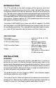
INTRODUCTION The X-75 and X-85 are the latest members of the Lowrance family that combines a high performance sonar with a wide, high definition screen. Using menu features and “soft-key” operation, these units are also easy to use. The wide screen shows the underwater world with high resolution and detail. The display and keyboard are also lighted for night operation. They have digital boat speed, surface water temperature, and distance travelled (log) screens.
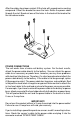
After the cables have been routed, fill the hole with a good marine sealing compound. Offset the bracket to cover the hole. Route the power cable through the slot. Break out one of the holes in the back of the bracket for the transducer cable. FRONT POWER CONNECTIONS The unit works from a twelve-volt battery system. For the best results, attach the power cable directly to the battery. You can attach the power cable to an accessory or power buss, however you may have problems with electrical interference.
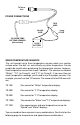
To Sonar Unit POWER CONNECTIONS RED WIRE BLACK WIRE TO SPEED/TEMP OR TEMP SENSORS (Not included) 3 amp FUSE 12 VOLT BATTERY SPEED/TEMPERATURE SENSORS This unit accepts up to three temperature sensors which can monitor surface water, live well, air, and virtually any other temperature. You do need to be careful when purchasing the temperature sensors, however. Each temperature sensor has its own "address". The sensors are labeled "Water", "T-2" (or Temp-2), and "T-3" (or Temp-3).
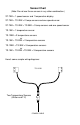
Sensor Chart (Note: Do not use these sensors in any other combination.
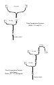
TS-12 BK TS-3 BK Three Temperature Sensors (Water, T-2, and T-3) POWER CABLE ST-TBK TS-2 BK TS-3 BK Three Temperature Sensors plus Speed (Water, T-2, T-3, and Speed) POWER CABLE
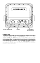
LOWRANCE 192 kHz TRANSDUCER POWER TO SAM-50HPD (NOT INCLUDED) CONNECTORS The diagram above shows the three connectors on the back of the sonar unit. Looking at the back of the unit, the 192 kHz transducer connector is at the far left. Plug the 192 kHz transducer in here. The center connector is for the power cable. The connector at the far right is for a serial cable that is included with the SAM-50HPD. This is the cable that allows the SAM to communicate with the sonar unit.
Transducer Installation Some of the models covered by this manual have a transom-mount transducer included. There two different transducers that could be packed with your unit. One is a 20° cone angle "Skimmer" transducer that can be mounted on the transom or epoxied inside certain boats to "shoot-thru" the hull. The other transducer is an 8° cone angle "Skimmer" transducer that is transom-mounted only.
Shoot-thru-hull v.s. Transom Mounting (20° Transducer Only) Typically, shoot-thru-hull installations give excellent high speed operation and good to excellent depth capability. There is no possibility of damage from floating objects. It can't be knocked off when docking or loading on the trailer. However, the shoot-thru-hull installation does have its drawbacks. One, some loss of sensitivity does occur, even on the best hulls.
2. Slide the transducer between the two ratchets. Temporally slide the bolt though the transducer assembly and hold it against the transom. Looking at the transducer from the side, check to see if it will adjust so that its face is parallel to the ground. If it does, then the “A” position is correct for your hull. If the transducer’s face isn’t parallel with the ground, remove the transducer and ratchets from the bracket.
CAUTION! CLAMP THE TRANSDUCER CABLE TO TRANSOM NEAR THE TRANSDUCER. THIS WILL HELP PREVENT THE TRANSDUCER FROM ENTERING THE BOAT IF IT IS KNOCKED OFF AT HIGH SPEED. GOOD LOCATION POOR LOCATION POOR ANGLE GOOD LOCATION 4. Hold the transducer and bracket assembly against the transom. The transducer should be roughly parallel to the ground. The bottom of the transducer bracket should be in line with the bottom of the hull.
5. Remove the transducer from the bracket and re-assemble it with the cable passing through the bracket over the bolt as shown above. Attach the transducer to the transom. Slide the transducer up or down until it’s aligned properly on the transom as shown above. Tighten the bracket’s mounting screws. Adjust the transducer so that it’s parallel to the ground and tighten the lock nut until it touches the flat washer, then add 1/4 turn.
SHOOT-THRU-HULL (20° Transducer Only) The transducer installation inside a fiberglass hull must be in an area that does not have air bubbles in the resin or separated fiberglass layers. The sonar signal must pass through solid fiberglass. A successful transducer installation can be made on hulls with flotation materials (such as plywood, balsa wood, or foam) between layers of fiberglass if the material is removed from the chosen area.
TRANSDUCER LOCATION (HIGH SPEED) TRANSDUCER LOCATION (TROLLING SPEED) Shoot-thru-hull Installation (20° Transducer Only) 1. Make certain the area is clean, dry, and free of oil or grease, then sand both the inside surface of the hull and the face of the transducer with 100 grit sandpaper. The surface of the hull must be flat so the entire transducer face is in contact with the hull prior to bonding. SPREAD EPOXY HERE SAND THIS SURFACE 2.
TRANSDUCER INSTALLATION - 8° Transducer Only The 8° transducer is designed for transom mount only. It can be installed on any outboard or stern-drive powered boat. Do not use this transducers on an inboard powered boat. Please read these instructions carefully before installing your transducer. The transducer mounting location is the most critical part of a sonar installation. If it isn’t done properly, the sonar can’t perform to its potential. ASSEMBLY A 1.
TRANSDUCER BRACKET RATCHET TRANSDUCER RATCHET See the chart at the top of the next page for example transducer angles for letter "A" at 12, 14, and 16 degree transom angles. 14 DEGREES -o +o This is the way the transducer should look when it's mounted on the transom.
12 DEGREE TRANSOM ANGLE INDEX MARKS A-A +37.0 ANGLE OF ATTACK +22.0 IN DEGREES +6.0 (REF. BOTTOM OF HULL) -9.0 A-B +31.0 +16.0 -1.0 -14.0 A-C A-D +40.0 +35.0 +25.0 +20.0 +10.0 +4.0 -5.0 -11.0 A-E +28.0 +13.0 -2.0 -17.0 A-B +33.0 +18.0 +3.0 -12.0 A-C +42.0 +27.0 +12.0 -3.0 A-D +37.0 +22.0 +6.0 -9.0 A-E +30.0 +15.0 0.0 -15.0 A-B +35.0 +20.0 +5.0 -10.0 A-C +44.0 +29.0 +14.0 -1.0 A-D +39.0 +24.0 +8.0 -7.0 A-E +32.0 +17.0 +2.0 -13.0 PER RATCHET CLICK 14 DEGREE TRANSOM ANGLE INDEX MARKS A-A +39.
LOCK WASHER BOLT NUT FLAT WASHER FLAT WASHER 2. Once you've determined the proper ratchet placement, assemble the transducer and bracket as shown above. Don't tighten the nut at this time. INSTALLATION - Location 1. The transducer must be placed in a location that has a smooth flow of water at all times. Air bubbles created by the movement of the boat hull against the water interfere with the sonar signal. This causes “noise” or random marks to appear on the sonar’s display.
POOR LOCATION GOOD LOCATION POOR ANGLE GOOD LOCATION 3. Don’t mount the transducer directly behind strakes or ribs on the bottom of the hull. Typically, a good location on aluminum boats is between the ribs closest to the engine. 4. Once you determine the best location for the transducer, hold the bracket against the transom. The transducer should be roughly parallel to the ground. The bottom of the hull should be about halfway between the centerline of the transducer and its bottom.
6. Route the transducer cable to the sonar unit. Keep the transducer cable away from other wiring on the boat, if possible. Electrical noise from engine wiring or bilge pumps can be picked up on the transducer cable. This can show up as unwanted interference on the sonar display. FLAT-BOTTOM HULL DEEP-"VEE" HULL NOTE: Some aluminum boats with strakes or ribs on the outside of the hull create large amounts of turbulence at high speed.
KEYBOARD The keyboard has keys arranged in two vertical columns beneath the arrow keys. The menu key near the bottom left corner of the keyboard activates the first menu page. The other keys are used to activate the alarm menu, make menu selections, and change modes. MODE - Pressing this key switches the unit between different modes. MENU - Press this key to show the menus and gain access to most functions. ARROW KEYS - These keys are used to make menu selections and to move objects on the screen.
OPERATION POWER/LIGHTS To turn the unit on, simply press the PWR key. A screen similar to the one at right appears. The PWR key also controls the lights. Once the it's turned on, press the PWR key to turn the lights on. Press the PWR key again to turn the lights off. To turn the sonar unit off, press and hold the PWR key while a "countdown" appears on the screen. The unit will shut itself off when the countdown reaches zero. Release the PWR key.
When the single frequency mode is enabled, as shown at right, adjusting sensitivity or grayline is straightforward. Simply press the MENU key, then press the up or down arrow keys until the desired menu appears, then make the adjustment using the left or right arrow keys. However, you can adjust some features separately when you're using both 50 and 192 kHz. For example, the sensitivity menu shown at right lets you select either the 192 or 50 kHz chart by pressing the appropriate arrow key.
MODES This unit has five different modes: FASTRAK, digital/chart, split-chart, full chart, and window groups. Each of these modes also has multiple options. To select a different mode, first press the MODE key. A screen similar to the one at right appears. Press the up or down arrow key to select the desired mode, then press the left or right arrow key to select an option from that mode, if necessary. Press the EXIT key to erase the menu.
Split Chart The split chart normally shows the underwater world from the surface to the bottom on the right side of the screen. The left side shows an enlarged version of the right side. The zoom range shows at the bottom of the screen. In the split 192 kHz example screen shown at right, the zoom range is 2X, or two times the right side's view. By pressing the ZOUT and ZIN keys, you can change the left side's zoom from 2X to 4X and back.
the left or right arrow keys to sequence through the available groups. When the desired group appears, press the EXIT key to erase the modes menu. Reprogram Windows Groups You can customize the window groups to meet your own fishing or boating situations. This unit gives you eight different windows that can be rearranged into many combinations. To reprogram a group, first go to the "System Setup" menu as shown at right. Next, highlight the "Reprogram Groups" label and press the right arrow key.
Reset Window Groups To return all groups to the factory settings, use the "Preset Options" on the "System Setup" menu. To return only one group to its factory setting, select "reprogram groups" from the "System Setup" menu. The screen shown below right appears. Press the left or right arrow key until the desired window group that you want to reset appears. When it appears, simply press the down arrow key and the unit will reset only that group. Press the EXIT key to erase the menu.
SENSITIVITY The sensitivity controls the ability of the unit to pick up echoes. A low sensitivity level excludes much of the bottom information, fish signals, and other target information. High sensitivity levels enables you to see this detail, but it can also clutter the screen with many undesired signals. Typically, the best sensitivity level shows a good solid bottom signal with Grayline and some surface clutter.
RANGE - Automatic When turned on for the first time, the unit automatically places the bottom signal in the lower half of the screen. This is called Auto Ranging and is part of the automatic function. Typically, the range cannot be changed manually while the unit is in automatic, as shown at right. However, depending upon the bottom depth and the current range, you can change the range to a different depth.
UPPER AND LOWER LIMITS You can enter any range when the unit is in the manual mode. The unit lets you enter any upper and lower limit, provided there is at least five feet separating them, for example, from 20 to 25 feet. (On the screen below left, the upper limit is 0 and the lower limit is 60.) Using the upper and lower limit range option, we changed the range from 0 to 60 feet to 24 to 54 feet. This "zoomed" the display to a 30 foot range.
In this example, we're setting the upper limit. Use the up and down arrow keys to select the number, the right and left arrow keys to move to the next number. When the limit shows the desired depth, press the ENT key. The screen shown below appears. As you can see, the upper limit has changed from 0 to 35 feet. With the lower limit remaining at 60 feet, this gives a "zoom" of 25 feet.
ZOOM - MANUAL MODE The Z-IN (zoom-in) and Z-OUT (zoom-out) keys enlarge and reduce the size of the echoes on the screen when the unit is in the manual mode, the same as the automatic mode. However, you can manually adjust the zoom when the unit is in the manual mode. To do this, press the MENU key, then press the right or left arrow keys until the "CHART ZOOM" menu appears. Now press the right arrow key. A screen similar to the one at right appears. This is the split-screen zoom menu.
down arrow keys until the GRAYLINE menu appears. A screen similar to the one at right appears. Press the left arrow key to decrease the gray level or the right arrow key to increase it. The percentage of GRAYLINE in use changes as the arrow keys are pressed. The bar chart also gives a graphical indication of the GRAYLINE level. You can see the change on the screen (both on the menu and on the chart record) as you press the keys. After you’ve finished, press the EXIT key to erase the menu.
FISH ID The Fish ID feature identifies targets that meet certain conditions as fish. The microcomputer analyses all echoes and eliminates surface clutter, thermoclines, and other signals that are undesirable. In most instances, remaining targets are fish. The Fish ID feature displays symbols on the screen in place of the actual fish echoes. There are four fish symbol sizes: tiny, small, medium, and large. These are used to designate the relative size between targets.
When the unit is first turned on, FishTrack is off. To turn the FishTrack feature on, press the menu key, then press the up or down arrow keys until the FISH ID menu appears. Now press the right arrow key. Pressing it once switches the Fish ID feature on, but leaves FishTrack off. To turn FishTrack on, press the right arrow key again, which highlights the "TRACK" label on the Fish ID menu. CHART SETUP You can customize the chart screen.
To turn the chart cursor off, repeat the above steps. The unit returns to the sonar screen without the chart cursor. DISPLAY ZOOM BAR When the unit is in the split-screen zoom mode, the zoom bar doesn’t normally show on the screen. The zoom bar shows the section of water on the right side of the screen that is being enlarged on the left side. To turn the zoom bar on continuously when the split-screen mode is on, highlight the "Show Zoom Bar" on the "Chart Setup" menu, then press the right arrow key.
The digital normally operates at 192 kHz, however, to penetrate deeper water, you can switch it to 50 kHz. The digital's frequency shows just to the right of the digital depth display. The digital sonar can be turned off, however this turns all automatic features off also, such as auto sensitivity, auto ranging, depth alarms, and the Fish ID. feature. Note: The digital sonar is turned off when the FASTRAK mode is turned on. You can change the digital's frequency, if the optional SAM-50HPD is installed.
setting. Both depth alarms work only off the digital bottom depth signals. No other targets will trip these alarms. If you turn the digital off, the depth alarms will be inoperative. These alarms can be used at the same time or individually. CAUTION! The depth alarms are turned off when the FASTRAK mode is turned on! To adjust the shallow alarm, highlight the "Shallow Depth" label. To adjust the deep alarm, highlight the "Deep Depth" label. Both alarms adjust identically.
ZONE ALARM The zone alarm is triggered when any echo passes inside the zone alarm bar, shown on the right side of the screen. To turn the zone alarm on, highlight the "Zone Alarm" label on the alarms menu, then press the right arrow key. To adjust the zone alarm, highlight the "Zone Adjust" label, then press the right arrow key. A screen similar to the one at right appears.
sensitivity of the receiver, decreasing it near the surface and gradually increasing it as the depth increases. The maximum depth that SCC will affect is 75% of the selected depth range. For example, on a 0-60 foot range with maximum SCC, surface clutter will be reduced down to 45 feet. There are three levels of SCC available: low, medium, and high. When it’s turned on for the first time, the SCC level is low.
SYSTEM SETUP The following features are available through the "System Setup" menu. To access this menu, press the MENU key, then press the up or down arrow keys until the "System Setup" menu appears. Press the right arrow key. The screen shown at right appears. Audio/Display You can adjust the display's contrast, turn the speaker off or on, and adjust the light intensity using this menu. To do this, highlight the "Audio/Display" label on the system setup menu, then press the right arrow key.
Temperature Graph Some of the screens have a temperature graph, as shown at right. Normally, the temperature graph has a 2° range. On the screen shown at right, the temperature graph has a range from 71° to 73°. You can change this range to 4° or 10° using the "Temp Graph Scale" label on the Units of Measure menu. Highlight that label, then press the right arrow key until the desired temperature graph range is highlighted. Press the EXIT key to erase the menu.
Press the right arrow key, then the up or down arrow keys until 1.0 appears in the "Adj Keel" box, as shown at right, then press the ENT key. This immediately changes the digital depth display at the top of the screen by one foot. Press the EXIT key to erase this menu. Note: Another way to use the keel offset feature is if you want to know the depth of the water below the lowest part of the boat, instead of the surface. To do this, measure the lowest part of the boat below the transducer.
WINDOWS SUMMARY GROUP "A" GROUP "B" GROUP "C" GROUP "D" GROUP "E" GROUP "F" GROUP "G" GROUP "H"
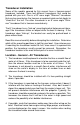
TROUBLESHOOTING If your unit is not working, or if you need technical help, please use the following troubleshooting section before contacting the factory customer service department. It may save you the trouble of returning your unit. Unit won’t turn on: 1. Check the power cable’s connection at the unit. Also check the wiring. 2. Make certain the power cable is wired properly. The red wire connects to the positive battery terminal, black to negative or ground. 3. Check the fuse. 4.
3. The water may be deeper than the sonar’s ability to find the bottom. If the sonar can’t find the bottom signal while it’s in the automatic mode, the digital will flash continuously. It may change the range to limits far greater than the water you are in. If this happens, place the unit in the manual mode, then change the range to a realistic one, (for example, 0-100 feet) and increase the sensitivity. As you move into shallower water, a bottom signal should appear. 4. Check the battery voltage.
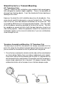
NOISE A major cause of sonar problems is electrical noise. This usually appears on the sonar’s display as random patterns of dots or lines. In severe cases, it can completely cover the screen with black dots, or cause the unit operate erratically, or not at all. To eliminate or minimize the effects of electrical noise, first try to determine the cause. With the boat at rest in the water, the first thing you should do is turn all electrical equipment on the boat off. Make certain the engine is off, also.
LOWRANCE ELECTRONICS FULL ONE-YEAR WARRANTY “We", “our”, or “us” refers to LOWRANCE ELECTRONICS, the manufacturer of this product. “You” or “your” refers to the first person who purchases this product as a consumer item for personal, family, or household use. We warrant this product against defects or malfunctions in materials and workmanship, and against failure to conform to this product’s written specifications, all for one year (1) from the date of original purchase by you.
How to Obtain Service (Canadian Customers Only) We back your investment in quality products with quick, expert service and genuine Lowrance replacement parts. If you need service or repairs, contact the Lowrance Factory Customer Service Department at the toll-free number listed below. A technician may be able to solve the problem and save you the inconvenience of returning your unit. You will be asked for your unit's serial number. 800-324-1356 Canada Only. Monday through Friday 8:00 A.M. - 8:00 P.M.
How to Obtain Service (U.S.A. Only) We back your investment in quality products with quick, expert service and genuine Lowrance® replacement parts. If you're in the United States and you have questions, please contact the Factory Customer Service Department using our toll-free number listed below. You must send the unit to the factory for warranty service or repair. Please call the factory before sending the unit. You will be asked for your unit's serial number.