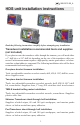
988-0176-06_A HDS unit installation instructions Read the following instructions carefully before attempting any installation. Transducer installation recommended tools and supplies (not included) If you plan to route the transducer cable through the transom, you will need either a 1" drill bit or a 5/8" drill bit depending on the size of the transducer cable connector. Each transom mount requires a high quality, marine grade above- or belowwaterline sealant/adhesive compound.
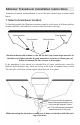
Skimmer Transducer installation instructions Transducer location and installation is one of the most critical steps in sonar installation. 1. Select a transducer location To function properly the Skimmer transducer must be in the water at all times and in a location that has a smooth flow of water when the boat is moving. Poor location Good location Poor location Good location Aluminum boats with strakes or ribs on the hull can create large amounts of turbulence at higher speeds.
2. Aligning Ratchets on Transducer bracket Aligning ratchets on one-piece bracket: The one-piece bracket assembly includes two black plastic ratchets. The ratchets are used to align the transducer with the boat hull. Each ratchet has the letters A-E molded into it. Ratchet Bracket 1. Insert the ratchets in the bracket with the letter "A" aligned with the dot stamped on the outside of the transducer bracket, as shown in the following series of diagrams. Align dot and letter "A". 2.
Aligning ratchets on two-piece bracket: The two-piece bracket includes four black plastic ratchets. The ratchets are used to align the transducer with the boat hull. Each ratchet has the letters A-F molded into it. Ratchet 1. Place two of the ratchets in each side of the bracket with the letter "A" aligned with the alignment mark molded into each bracket. 2. Now place the other two ratchets on the transducer with the letter "A" aligned in the 12 o'clock position on the transducer stem.
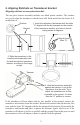
3. Assembling the Transducer bracket After determining the correct position for the ratchets, loosely assemble the transducer and bracket assembly as shown in one of the two diagrams below. One-piece bracket assembly: Metal washer Lock nut Rubber washers Metal washer Ratchets Bolt Do not tighten the transducer bracket assembly until you have aligned the transducer and bracket on the transom.
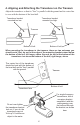
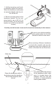
4. Aligning and Attaching the Transducer on the Transom Adjust the transducer so that its "face" is parallel with the ground and its center line is even with the bottom of the boat hull. Transducer bracket mounted too high. Transducer bracket mounted too low. Transom Transom Bottom of hull. Bottom of hull. When mounting the transducer to the transom, there are two extremes you should avoid, first, do not let the edge of the mounting bracket extend below the bottom of the hull, left image, above.
1. Hold the transducer and bracket assembly against the transom. When the transducer and bracket are properly aligned mark its position on the hull. 2. Drill the mounting holes for the transducer bracket. For the onepiece bracket use a #29 bit (for the #10 screws). For the two-piece bracket use a #20 bit (for the #12 screws). Use the provided screws to secure the transducer assembly to the transom. Be sure to use a below-waterline marine grade sealant on all of the transducer bracket screw holes.
If you drill a hole in the transom for the transducer cable, make sure it is located above the waterline. Seal the hole with an above or below waterline marine grade sealant. Route the transducer cable to the sonar unit. Make sure to leave some slack in the cable near the transducer. Use caution when routing the transducer cable near other wiring and cables.
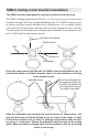
TMB-S trolling motor bracket installation The TMB-S bracket is designed for one-piece bracket transducers only. The TMB-S trolling motor bracket (Part No. 51-45) is an optional accessory and is available through LEI Extras at www.lei-extras.com. The TMB-S bracket is used to attach a one-piece bracket transducer to a trolling motor. If you regularly fish in water with a lot of underwater structure, such as rocks, stumps and trees, you may consider using a Pod transducer for trolling motor installation.
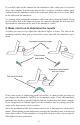
Skimmer Transducer shoot-thru-hull installation Before attempting any installation on boats with flotation material sandwiched within the hull, consult the boat manufacturer. In a shoot-thru-hull installation the transducer is epoxied to the inside of the boat hull. WARNING: Do not remove any material from the inner hull. Careless grinding or cutting on the hull could damage the integrity of the hull. Contact the boat dealer or manufacturer to confirm hull specifications.
A transducer can not shoot through wood or metal hulls. Wood and metal hulls require either a transom mount or "thru-hull" installation. For shoot-thru-hull applications many boat hulls have a flat keel pad that offers a good transducer mounting surface. If you are using a Skimmer transducer versus a Pod transducer for this installation, make sure the Skimmer transducer is oriented so the nose of the transducer is facing the bow (front) of the boat.
Pod Transducer installation instructions The following instructions explain how to install a Pod transducer inside a hull or on a trolling motor. Read the following instructions carefully before attempting any installation. Use extreme care when mounting a transducer inside a boat hull. Once epoxied into position, the transducer can be very difficult to remove. NOTE: Transducer location and installation is one of the most critical steps in sonar installation.
On vee hulls try to place the transducer where the deadrise is 10° or less. 1. Sand face of transducer and bottom of hull. 2. Apply epoxy to face of transducer and bottom of hull. Sand both the inside surface of the hull, where the transducer is to be epoxied, and the face of the transducer. You may want to start with a rougher grit sandpaper, such as 60 grit, and finish with a smoother grit, such as 160 grit, sandpaper. Sand the inside surface of the hull until it is smooth to the touch.
Pod Transducer trolling motor installation The top of the transducer is curved to fit the contour of the trolling motor. 1. Slide the hose clamp through the Pod transducer brackets, as shown below. You will need a hose clamp large enough to fit over the trolling motor. The hose clamp is NOT included with the Pod transducer. Before you attach the transducer to the trolling motor, make sure there is enough slack in the transducer cable for the trolling motor to turn freely. 2.
Transducer maintenance Periodically wash the face of the transducer with soap and water to remove any oil film or debris build-up. Oil and other materials on the transducer's face can hamper its performance. Cleaning will ensure longevity and proper performance of the device.
Mounting the Unit: Gimbal bracket or In-dash The unit comes with a gimbal bracket so you can mount it on a dash. The unit also ships with an in-dash template and four screws for in-dash installations. Determine the mounting location for the unit. Screws to secure the gimbal bracket to a dash are not included with the unit.
3. Use screws or bolts to secure the gimbal bracket to the mounting surface. 4. Pass all the cable connectors through the 1-inch hole in the center of the gimbal bracket. Leave enough slack in the cables to allow for tilting of the unit.
Gimbal bracket knob Gimbal bracket knob 4. Secure the unit to the gimbal bracket using the gimbal bracket knobs. Cable connectors Sockets Sockets 5. Match up the cable connectors to the sockets on the back of the unit. Each cable and socket is labeled. Attach the proper connector to each socket. Power up the unit to make sure all the connectors are securely fastened to the proper socket.
In-dash installation The unit ships with an in-dash template and four #6 – 20 X 1-1/2" screws. Before cutting any holes in the mounting surface make sure there is enough room to attach the cable connectors behind the unit. Begin by taping the in-dash template to the mounting surface. Use a #31 (0.120") drill bit for the four pilot holes.
To remove the rest of the material from the mounting surface (indicated by the shaded area) cut along these dotted lines. After cutting the four corner holes, use a saw to cut along the dotted lines from hole to hole. Be sure to cut along the inner dotted line, not the outer solid line. This diagram shows the sequence for securing the unit to the mounting surface. 1) Place the unit in the hole cut into the mounting surface. 2) Use the provided screws to secure the unit to the mounting surface.
Connectivity Combination Sonar/GPS units Sonar Power/Data ENET (Ethernet) Network GPS only units Power/Data ENET (Ethernet) 21 Network
Power / Data cable wiring diagram Unit The yellow wire is the Accessory Wake Up line. Power/Data cable Power cable (3 wire) Data cable (5 wire) Red (+) wire with fuse and fuse holder. Yellow TX (+) Blue TX (-) Orange RX (+) Black (-) wire Green RX (-) Shield (ground) The Data cable wires are used for the NMEA 0183 and RS-422 hook up; also, RS-232 and RS-422 for HDS-8 and HDS-10 models. Refer to the detailed drawings on the following pages.
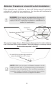
Multiple unit wiring diagram with devices Ethernet cables LBS-1 NEP-1 The four yellow wires (Acessory Wake Up lines) from each power cable should be wired together. Fuse and fuse holder. The red wire from each power cable should be fused between the device and the battery. The diagram above shows two HDS units and an LBS-1 connected via an NEP-1. The power cable from each device contains a yellow wire. The yellow wire is the Accessory Wake Up line. Connect the yellow wires together.
Data cable wiring diagram: HDS-8 & HDS-10 units NMEA 0183 wiring (data cable) To exchange NMEA 0183 data, the HDS-8 and HDS-10 units have a NMEA 0183 version 2.0 (RS-422) communication port. Serial Communications Port one (Com 1) can be used to transmit or receive NMEA format data. Two RS-232 ports (Com 1 and Com 2) also are available via software selection. These ports transmit or receive NMEA data.
Data cable wiring diagram: HDS-8 & HDS-10 units NMEA 0183 wiring (data cable) • Com 1 (RS-232) uses the yellow wire to transmit, orange wire to receive and shield (bare) wire for signal ground. • Com 2 (RS-232) uses the blue wire to transmit, green wire to receive and shield (bare) wire for signal ground.
Data cable wiring diagram: HDS-5 & HDS-7 units NMEA 0183 wiring (data cable) To exchange NMEA 0183 data, the HDS-5 and HDS-7 units have a NMEA 0183 version 2.0 (RS-422) communication port. Serial Communications Port one (Com 1) can be used to transmit or receive NMEA format data. The five wires for the serial communications ports (Data cable) are combined with the Power cable to form the Power/Data cable.
Blank Page 27
Visit our website: www.lowrance.