LSISAS6160 SAS Switch User Guide Revision 1.
Revision History Version and Date Revision 1.1, Septembre 2010 Description of Changes First channel release. LSI and the LSI logo are trademarks or registered trademarks of LSI Corporation or its subsidiaries. All other brand and product names may be trademarks of their respective companies. LSI Corporation reserves the right to make changes to the product(s) or information disclosed herein at any time without notice.
LSISAS6160 SAS Switch User Guide Table of Contents Table of Contents Chapter 1: Overview . . . . . . . . . . . . . . . . . . . . . . . . . . . . . . . . . . . . . . . . . . . . . . . . . . . . . . . . . . . . . . . . . . . . . . . . . . . . . . . . . . . . . . . . . . . . . . . . . . . . . . . . . . . . . . . . . . . . . . . .5 1.1 LSISAS6160 Switch Features . . . . . . . . . . . . . . . . . . . . . . . . . . . . . . . . . . . . . . . . . . . . . . . . . . . . . . . . . . . . . . . . . . . . . . . . . . .
Table of Contents LSISAS6160 SAS Switch User Guide 3.7 Devices Tab . . . . . . . . . . . . . . . . . . . . . . . . . . . . . . . . . . . . . . . . . . . . . . . . . . . . . . . . . . . . . . . . . . . . . . . . . . . . . . . . . . . . . . . . . . . . . . . . . . . . . . . . . . . . . . . . . . . .50 3.7.1 Properties Tab . . . . . . . . . . . . . . . . . . . . . . . . . . . . . . . . . . . . . . . . . . . . . . . . . . . . . . . . . . . . . . . . . . . . . . . . . . . . . . . . . . . . . . . . . . . . . .
Chapter 1: Overview | LSISAS6160 Switch Features LSISAS6160 SAS Switch User Guide Chapter 1 Overview This document is the primary reference for the LSISAS6160 Serial Attached SCSI (SAS) switch. It describes the features of the switch and explains how to perform installation and physical configuration of the switch. The document also explains how to use both the web-based, and the command-driven SAS Domain Manager (SDM) utility interfaces to create storage configurations in the SAS domain.
Chapter 1: Overview | Serial Attached SCSI and the SAS6160 Switch 1.2 Serial Attached SCSI and the SAS6160 Switch LSISAS6160 SAS Switch User Guide SAS replaces Ultra320 SCSI as the next phase in the evolution of the SCSI standard. The SAS interface addresses enterprise data storage and retrieval requirements with features such as point-to-point topology, 6.0Gb/s transfer rate, minimum arbitration overhead, native support for both SAS and SATA drives, and smaller cables and connectors.
Chapter 1: Overview | Serial Attached SCSI and the SAS6160 Switch LSISAS6160 SAS Switch User Guide The following figure shows how the SAS6160 switch centralizes management of all application servers and data storage devices in the SAS domain.
Chapter 1: Overview | Serial Attached SCSI and the SAS6160 Switch LSISAS6160 SAS Switch User Guide You can connect multiple SAS6160 switches in various topologies to provide failover support and to increase the number of connected devices in the SAS domain. The theoretical upper limit of SAS devices in a domain is 16,000. Each SAS6160 switch can handle 1000 SAS addresses. The following figure shows a high-level block diagram of the SAS6160 switch.
Chapter 1: Overview | SAS Phys, Ports, and Connectors LSISAS6160 SAS Switch User Guide 1.3 SAS Phys, Ports, and Connectors Flash Memory – Each LSISA2x36 expander connects to a parallel flash through the expander’s external memory interface. This flash is used for firmware storage and execution, as well as nonvolatile data such as Ethernet MAC address and SAS WWID.
Chapter 1: Overview | SAS Phys, Ports, and Connectors LSISAS6160 SAS Switch User Guide a. Narrow SAS Port with One Phy in Each Port Narrow Port Narrow Port TX Phy RX Phy b. Wide SAS Port with Four Phys in Each Port Wide Port Wide Port TX Phy RX Phy RX Phy RX Phy RX Phy TX Phy TX Phy TX Figure 5: Phy Narrow and Wide SAS Ports The SAS6160 switch has 64 phys, numbered 0 through 63.
Chapter 1: Overview | SAS Connectors and Cabling LSISAS6160 SAS Switch User Guide 1.4 SAS Connectors and Cabling Use a separate crossover cable for each server, JBOD, RAID array, switch, or other device connected to the SAS6160 switch. Use Mini SAS 4x connectors (also called SFF-8088 connectors) on both ends of the crossover cables to connect the switch to all devices. The keyed connectors at port 0 and port 2, located at the upper left on the SAS6160 switch, support active cabling.
Chapter 1: Overview | SAS Routing and Zoning 1.5 SAS Routing and Zoning LSISAS6160 SAS Switch User Guide SAS is a connection-oriented, point-to-point technology. When a host (initiator) issues a request to read or write data, the SAS6160 switch automatically determines how to route the connection request from the initiator to the correct data storage device (target).
Chapter 1: Overview | SAS Routing and Zoning LSISAS6160 SAS Switch User Guide The following figure shows a simple example of zoning. Figure 7: 1.5.2 Creating SAS Zones Simple Zoning Example You create SAS zones by first creating zone groups that include hosts or storage devices that share common access privileges, and zone sets that connect the zone groups together. Use the SDM utility to create zones. The SDM-GUI utility provides zoning wizards to create zone groups and zone sets automatically.
Chapter 1: Overview | SAS Routing and Zoning Page 14 LSISAS6160 SAS Switch User Guide A zone set must be active for its definitions to be applied to the SAS domain. Zone sets are activated in the SDM utility. Only one zone set can be active at one time. When no zone set is active, zoning is disabled and domain access is unrestricted.
Chapter 1: Overview | SAS Routing and Zoning LSISAS6160 SAS Switch User Guide 1.5.3 Configuring SAS Zones The following figure shows a sample configuration with three hosts and five JBODs. Figure 8: Configuration for Zoning Example Host 1 belongs to a local work group and accesses JBOD 1 as its primary resource. But Host 1 also accesses JBOD 2, JBOD 3, and JBOD 4, as a backup resource. Host 2 is a backup server, and has JBOD 2, JBOD 3, and JBOD 4 as its primary resource, but also accesses JBOD 1.
Chapter 1: Overview | Connecting Devices to the SAS6160 Switch LSISAS6160 SAS Switch User Guide To create a suitable configuration, run the SDM utility and create the zone groups shown in the following figure. Figure 9: Creating Zone Groups Next, use the SDM utility to assign the following permissions, by creating zone sets: 1.6 Connecting Devices to the SAS6160 Switch Zone group 6 accesses zone groups 8 and 9, and vice versa. Zone group 7 accesses zone groups 9 and 10, and vice versa.
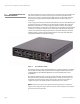
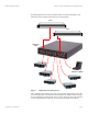
Chapter 1: Overview | Connecting Devices to the SAS6160 Switch LSISAS6160 SAS Switch User Guide — Four cascaded switches — A total of 64 total expanders in the topology The following examples show several ways in which you can connect devices to the SAS6160 switch. The first example (Figure 10) shows four servers (host bus adapters) and five JBODs connected to the SAS6160 switch. Figure 10: Example 1, Multiple Servers and JBODs A single rack can contain the switch and all the other devices.
Chapter 1: Overview | Connecting Devices to the SAS6160 Switch LSISAS6160 SAS Switch User Guide A separate cable with a Mini SAS connector on each end is used for each connection. All eight servers can access data on the RAID array. If more storage capacity is required in the future, the RAID array could be expanded, or a configuration with a second cascading switch could be created, as shown in the next example.
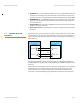
Chapter 1: Overview | Connecting Devices to the SAS6160 Switch LSISAS6160 SAS Switch User Guide The fourth example (Figure 13) shows a server connected through two SAS6160 switches to two input connectors on a JBOD for a high-availability configuration. Figure 13: Example 4, High Availability This dual porting configuration provides the server a redundant path through the switches for high availability.
Chapter 1: Overview | Connecting Devices to the SAS6160 Switch LSISAS6160 SAS Switch User Guide The fifth example (Figure 14) shows a large data storage network that includes two SAS6160 switches and several expanders. NOTE: Expanders are either zoning expanders or nonzoning expanders. When SAS drives are attached to a zoning expander, each drive can be zoned individually and each drive can be in its own zone group. When SAS drives are attached to a nonzoning expander, they cannot be zoned individually.
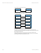
Chapter 1: Overview | Connecting Devices to the SAS6160 Switch LSISAS6160 SAS Switch User Guide The sixth example (Figure 15) shows a daisy chain, or cascaded, switch configuration, with four SAS6160 switches. This example assumes that various SAS targets and SAS initiators are attached to the other connectors on the switches. Figure 15: Example 6, Cascaded Switches Like in Example 3, the cables in this example can run from any connector of the downstream switch to any connector in the switch above it.
Chapter 1: Overview | Connecting Devices to the SAS6160 Switch LSISAS6160 SAS Switch User Guide Example 7 (Figure 16) shows a star (tree) configuration of four switches, with switch B, switch C, and switch D connected directly to switch A. Like in Example 6, this example assumes that various SAS targets and SAS initiators are attached to the other connectors on the switches.
Chapter 2: Installation and Hardware Setup | Unpacking the Switch LSISAS6160 SAS Switch User Guide Chapter 2 Installation and Hardware Setup This chapter explains how to unpack the LSISAS6160 SAS switch, install it on an optional rack shelf, connect power cables and other cables to it, change the default Static IP address, and connect SAS storage devices to it. This chapter also explains how to interpret the LEDs on the switch. 2.
Chapter 2: Installation and Hardware Setup | Installing the SAS6160 Switch 2.2.1 SAS6160 Connectors LSISAS6160 SAS Switch User Guide All 16 connectors on the SAS6160 switch accept standard passive SAS cabling. The connectors at port 0 and port 2 are active, which allows longer cable lengths when using active SAS cabling. See Chapter 1 for an explanation of SAS connectors and cables. Table 1: SAS Cable Lengths Connectors 1 and 3 - 15 0 and 2 only 2.2.2 SAS6160 LEDs Min. Length Max.
Chapter 2: Installation and Hardware Setup | Installing the SAS6160 Switch LSISAS6160 SAS Switch User Guide 2.3.1 Installing the SAS6160 Self A special shelf is available for mounting one or two SAS6160 switches in a standard rack. These options are shown in the following figure. Figure 2: One or Two SAS6160 Switches on a Rack Mounted Shelf To assemble and mount the shelf in a rack, follow these steps: 1. Unpack the SAS6160 shelf.
Chapter 2: Installation and Hardware Setup | Installing the SAS6160 Switch LSISAS6160 SAS Switch User Guide 3. Bolt the shelf onto the vertical rails in the rack, as shown in the following figure. Figure 4: Mounting Shelf in a Rack The mounting ears on the shelf rails are threaded, so place them on the inside of the vertical rack rails, and insert the bolts from the outside, as shown. The mounting ears on the shelf itself are not threaded, so mount them with clip nuts. 4.
Chapter 2: Installation and Hardware Setup | Connecting to a Host LSISAS6160 SAS Switch User Guide 2.4 Connecting to a Host To connect the SAS6160 switch to a host, follow these steps: 1. The 10/100 Ethernet connector (RJ-45 connector) on the connector side of the switch provides access to the embedded SDM Domain Manager utility. Use this utility to configure and manage the switch. — Use a standard RJ-45 cable, if connecting to an external Ethernet hub or switch.
Chapter 2: Installation and Hardware Setup | Changing the Default Static IP Address LSISAS6160 SAS Switch User Guide 7. Exit SDM-GUI and power cycle the switch. Using SDM-CLI 1. Login to SDM-CLI using the admin account. 2. Enter the following command: device ip static for example device 500605b0002453f ip static 172.21.25.204 255.255.255.0 172.21.25.1 3. Exit SDM-CLI and power cycle the switch. 2.5.2 Setting a Dynamic IP Address Using SDM-GUI 1.
LSISAS6160 SAS Switch User Guide 2.6 Connecting SAS and SATA Hardware Chapter 2: Installation and Hardware Setup | Connecting SAS and SATA Hardware The SAS6160 switch centralizes management for all SAS initiators and SAS targets in the SAS domain. The SAS ports on the SAS610 switch are by default both in ports and out ports. Depending on the requirements, you can attach each port to a SAS host bus adapter, a SAS or SATA JBOD, a RAID array, or a SAS expander.
Chapter 2: Installation and Hardware Setup | Safety Notices 2.7.2 Canada Mark 2.7.3 VCCI 2.7.
Chapter 2: Installation and Hardware Setup | Safety Notices LSISAS6160 SAS Switch User Guide 2.7.
Chapter 2: Installation and Hardware Setup | Safety Notices Page 32 LSISAS6160 SAS Switch User Guide LSI Corporation | September 2010
Chapter 3: SAS Domain Manager Graphical User Interface | SDM-GUI Accounts LSISAS6160 SAS Switch User Guide Chapter 3 SAS Domain Manager Graphical User Interface This chapter explains how to use the SAS Domain Manager Graphical User Interface (SDM-GUI) application to configure and monitor storage configurations with the LSISAS6160 SAS switch. The SDM-GUI utility is a Java Web Start application, and the LSISAS6160 SAS switch functions as an HTTP server that launches it.
Chapter 3: SAS Domain Manager Graphical User Interface | Summary Tab and Menu Options 3.3 Summary Tab and Menu Options LSISAS6160 SAS Switch User Guide The following figure shows the SDM-GUI main window, with the menu bar and Summary tab. Figure 1: SDM-GUI Summary Window The Summary tab indicates the IP address of the device SDM is currently accessing, as well as the domain status and domain ID, and the overlay name.
Chapter 3: SAS Domain Manager Graphical User Interface | File, Server, and Help Menu Options LSISAS6160 SAS Switch User Guide 3.4 File, Server, and Help Menu Options LSI Corporation | September 2010 The menu bar at the top of the window provides you several options for managing the server. The available commands are as follows: Select File >> Refresh to scan the domain for topology or status changes. (SDM automatically scans the domain once a minute.) Select File >> Exit to exit SDM-GUI.
Chapter 3: SAS Domain Manager Graphical User Interface | Views Tab LSISAS6160 SAS Switch User Guide 3.5 Views Tab The Views tab enables you to view information about the current domain. You can view information about the end device table, the alias table, zone groups, and zone sets. This information is available to both admin and user accounts. 3.5.
Chapter 3: SAS Domain Manager Graphical User Interface | Views Tab LSISAS6160 SAS Switch User Guide 3.5.2 View Alias Table As shown in the following figure, the View Alias Table option displays a list of all aliases.
Chapter 3: SAS Domain Manager Graphical User Interface | Views Tab 3.5.3 View Zone Groups As shown in the following figure, the View Zone Groups option displays a list of zone groups. To view details about any zone group, select it in the list on the left. An asterisk at the end of a zone group name indicates that the zone group is currently active.
Chapter 3: SAS Domain Manager Graphical User Interface | Views Tab LSISAS6160 SAS Switch User Guide 3.5.4 View Zone Sets As shown in the following figure, the View Zone Sets option displays a list of zone sets. To view details about any zone set, select it in the list on the left. An asterisk at the end of a zone set name indicates that the zone set was active at the time of activation.
Chapter 3: SAS Domain Manager Graphical User Interface | Domain Tab LSISAS6160 SAS Switch User Guide 3.6 Domain Tab The Domain tab, which is available only in the admin account, has commands that manage aliases, zone groups, and zone sets. In addition, it has several wizards for domain configuration and management tasks. To use the specific commands described in this section, click the hyperlinks on the Domain tab. 3.6.
Chapter 3: SAS Domain Manager Graphical User Interface | Domain Tab LSISAS6160 SAS Switch User Guide Alias names must be unique and must not resemble valid SAS addresses (16 hexadecimal characters that start with the number 5). The only special characters you can use in an alias are pound (#), dash, and underscore. The tree displays aliases only for the devices presently in the domain. To see aliases for other devices, use the View/Delete Aliases command. 3.6.1.
Chapter 3: SAS Domain Manager Graphical User Interface | Domain Tab LSISAS6160 SAS Switch User Guide If the topology supports the configuration, the wizard builds two zone groups: one for the initiators, and one for the targets, with the names + #001 and + #002. The wizard scans through the domain and assigns to one zone group all the ZPSDS entry point phys that are upstream from initiators.
LSISAS6160 SAS Switch User Guide 3.6.2.3 End Device Wizard Chapter 3: SAS Domain Manager Graphical User Interface | Domain Tab Use the End Device Wizard to automatically configure a zone set and associated zone groups by grouping end devices. Each window of the wizard includes instructions to guide you through the configuration process. This wizard uses a snapshot of the current domain to determine the available end devices and then displays lists of initiators and targets.
Chapter 3: SAS Domain Manager Graphical User Interface | Domain Tab 3.6.3 Manually Configure Zone Groups 3.6.3.1 Create Zone Group LSISAS6160 SAS Switch User Guide The Manually Configure Zone Groups commands allow you to manually create, view, modify, and delete zone groups. This command provides greater control of zone set creation, and allows an administrator to edit an existing zone set or zone group. Use the Create Zone Group command to manually create zone groups.
Chapter 3: SAS Domain Manager Graphical User Interface | Domain Tab LSISAS6160 SAS Switch User Guide 3.6.3.2 View Zone Group Use the View Zone Groups command to view information about zone groups. To view details about any zone group, select the group from the pull-down list on the left. An asterisk at the end of a zone group name indicates that the zone group was active at the time of activation. Figure 4 shows the View Zone Group window. 3.6.3.
Chapter 3: SAS Domain Manager Graphical User Interface | Domain Tab 3.6.4 Manually Configure Zone Sets 3.6.4.1 Change Zone Manager Password LSISAS6160 SAS Switch User Guide The Manually Configure Zone Sets commands enable you to manually create, view, activate/deactivate, and delete zone sets. Use the Change Zone Manager Password command to change the password used to manage the zoning expanders in the domain. When the window appears, type the current password in the indicated field.
Chapter 3: SAS Domain Manager Graphical User Interface | Domain Tab LSISAS6160 SAS Switch User Guide 3.6.4.3 View Zone Set Use the View Zone Set command to view information about zone sets. To view details about any zone set, select it in the list on the left. An asterisk at the end of a zone set name indicates that the zone set was active at the time of activation. Figure 5 shows the View Zone Set window. 3.6.4.4 Modify Zone Set Use the Modify Zone Set command to modify existing zone sets.
Chapter 3: SAS Domain Manager Graphical User Interface | Domain Tab 3.6.4.5 Activate/Deactivate Zone Set LSISAS6160 SAS Switch User Guide Use the Activate/Deactivate Zone Set command to activate or deactivate a zone set. Only one zone set can be active at a time, and a zone set must be active for its definitions to be applied to the domain. Changes to the active zone set or zone group permissions do not take effect until the next zone set activation.
Chapter 3: SAS Domain Manager Graphical User Interface | Domain Tab LSISAS6160 SAS Switch User Guide 3.6.4.6 Delete Zone Set Use the Delete Zone Set command to delete an existing zone set. As shown in the following figure, you delete a zone set by selecting the zone set from the list on the left of the window and then clicking Delete.
Chapter 3: SAS Domain Manager Graphical User Interface | Devices Tab 3.7 Devices Tab LSISAS6160 SAS Switch User Guide The Devices tab displays the topology of the current domain in the form of a tree. When you select items on the tree, you access a secondary set of tabs, including Properties, Environmentals, Attached Devices, and Phys. The tabs displayed on this row depend on both the account type and the device selected in the tree.
Chapter 3: SAS Domain Manager Graphical User Interface | Devices Tab LSISAS6160 SAS Switch User Guide 3.7.1 Properties Tab As Figure 14 shows, the Properties tab displays information about the currently selected device in the tree in the left panel. Properties information includes SAS Address, Vendor ID, and Device Type. The rest of the displayed information varies, depending on the type of the selected device. In Figure 14, the domain properties are shown. The following figure shows the Properties tab.
Chapter 3: SAS Domain Manager Graphical User Interface | Devices Tab 3.7.2 Environmentals Tab The Environmentals tab appears for devices that contain SCSI Enclosure Services (SES) targets. The following figure shows an example of the type of data that appears on this tab. Environmental data, for each device that supports an SES target, is polled in a background loop.
Chapter 3: SAS Domain Manager Graphical User Interface | Devices Tab LSISAS6160 SAS Switch User Guide 3.7.3 Attached Devices Tab The Attached Devices tab appears for all expanders and end devices. This tab shows a list of devices directly connected to the selected device and the phys used in those connections. The following figure shows the Attached Devices tab.
Chapter 3: SAS Domain Manager Graphical User Interface | Devices Tab 3.7.4 Phys Tab LSISAS6160 SAS Switch User Guide The Phys tab appears for expanders. It lists information about the phys on the selected expander. The following figure shows the Phys tab. Figure 18: Phys Tab To view detailed information about any phy, click on an entry in the Phy ID column. A pop-up window appears with detailed status information.
Chapter 3: SAS Domain Manager Graphical User Interface | Devices Tab LSISAS6160 SAS Switch User Guide 3.7.5 Zone Group Tab The Zone Group tab becomes active if there is an active zone set, and if you click on an end device. In the following figure, the Zone Group tab is active because the selected initiator is a member of an active zone set. In the device tree, the devices that may communicate appear in blue.
Chapter 3: SAS Domain Manager Graphical User Interface | Devices Tab 3.7.6 Operations Tab The Operations tab appears only when you select an expander from an admin account. This tab contains the following commands. Figure 20: 3.7.6.1 Update Firmware LSISAS6160 SAS Switch User Guide Operations Tab Use the Update Firmware command to update the firmware on LSI SAS expanders, LSI SAS2 expanders, and LSI SAS2 switches. SDM verifies that the product identification of the image matches the targeted device.
Chapter 3: SAS Domain Manager Graphical User Interface | Devices Tab LSISAS6160 SAS Switch User Guide 3.7.6.2 Phys Enable/Disable/Reset Use the Enable/Disable/Reset Phys command to enable, disable, or reset specified expander phys. To disable one or more phys, remove the check mark in the Enabled column and click Apply. To reset one or more phys, select the check box in the Reset column and click Apply. The phys are automatically enabled after a switch reset.
Chapter 3: SAS Domain Manager Graphical User Interface | Devices Tab 3.7.6.4 Page 58 Configure IP LSISAS6160 SAS Switch User Guide Use the Configure IP command to change the IP address for the LSI SAS2 switch that is currently selected in the device tree. You can set either a static or a dynamic IP address as shown in the following figures.
Chapter 4: SAS Domain Manager Command Line Interface | Command Usage and Syntax LSISAS6160 SAS Switch User Guide Chapter 4 SAS Domain Manager Command Line Interface This chapter explains how to use the commands supported by the SAS Domain Manager Command Line Interface (SDM-CLI) with the LSISAS6160 SAS switch. SDM-CLI can be accessed using a telnet client.
Chapter 4: SAS Domain Manager Command Line Interface | SDM-CLI Commands 4.2 SDM-CLI Commands LSISAS6160 SAS Switch User Guide There are two types of SDM-CLI commands: Extra-Domain commands manage SDM-D itself and to control the domain focus of the Intra-Domain commands. Intra-Domain commands manage a single domain at a time. Each command description indicates whether the command is Extra-Domain or Intra-Domain. NOTE: You can use shortcuts when you type commands.
Chapter 4: SAS Domain Manager Command Line Interface | SDM-CLI Commands LSISAS6160 SAS Switch User Guide 4.2.3 Passwd Command (Extra-Domain) Use the passwd command to change the password for an account after prompting for the admin password. Passwords must have between four and 16 characters. Authority: Admin Syntax: passwd (admin | user) Usage: passwd admin Starts a dialog to change the password for the admin account.
Chapter 4: SAS Domain Manager Command Line Interface | SDM-CLI Commands LSISAS6160 SAS Switch User Guide Usage: 4.2.6 Device Command alias create Creates an alias that is bound to a specific device within the domain. The alias name can have a maximum of 24 characters. Valid characters are 0 through 9, A through Z, a through z, # (pound), - (dash), and _ (underscore). An alias name must not closely resemble a valid SAS address (16 hexadecimal characters that start with a 5).
Chapter 4: SAS Domain Manager Command Line Interface | SDM-CLI Commands LSISAS6160 SAS Switch User Guide 4.2.7 Show Command (Intra-Domain) Use the show command to display domain, device, and phy information. (See Section 4.3, Sample Output for Show Command, to view samples of the kind of information that is returned.
Chapter 4: SAS Domain Manager Command Line Interface | SDM-CLI Commands 4.2.8 Zonegroup Command LSISAS6160 SAS Switch User Guide (Intra-Domain) Use the zonegroup command to manage zone groups and zone group membership. Zonegroup commands have no effect on the active zone set until you reactivate it.
Chapter 4: SAS Domain Manager Command Line Interface | SDM-CLI Commands LSISAS6160 SAS Switch User Guide 4.2.9 Zoneset Command (Intra-Domain) Use the zoneset command to manage zone sets and zone set membership. NOTE: Only the zoneset activate and zoneset deactivate commands affect the state of the active zone set. Other zone group commands and zone set commands have no effect until you subsequently activate the zone set.
Chapter 4: SAS Domain Manager Command Line Interface | Sample Output for Show Command LSISAS6160 SAS Switch User Guide NOTE: Zoning within the domain is disabled when no zone set is active, and access is unrestricted. Therefore, all end devices in the domain can see one another. zoneset delete single Deletes a single zone set. zoneset delete all [noconfirm] Deletes all zone sets. If you specify the [noconfirm] option, the action occurs immediately without an additional confirmation prompt.
LSISAS6160 SAS Switch User Guide Chapter 4: SAS Domain Manager Command Line Interface | Sample Output for Show Command Device Parent ================================================ ================================ Num Alias / Alias / Type Phys SAS Address Phys SAS Address Phys ------------------------------------------------ -------------------------------Switch 64+2 Tchoupitoulas End 01 500062b10000417d 00 Tchoupitoulas 64 Switch 64+2 Poydras 00-01-02-03 Tchoupitoulas 00-01-02-03 End 04 Bacchus 00-01-02
Chapter 4: SAS Domain Manager Command Line Interface | Sample Output for Show Command Device Phys: Parent SAS Address: Parent Phys: Vendor Specific (hex): Vendor Specific (ASCII): LSISAS6160 SAS Switch User Guide 32-33-34-35 500062b10000127f 16-17-18-19 00 00 00 00 00 00 00 00 - Environmentals Information Last Update: Time Not Supported Chip Temperature: OK, 68 Celsius Board Temperature: OK, 44 Celsius Astek-Brann: OK Expander: OK J1:Interconnect 32-35: OK, SAS Mini 4i Plug J2:Uplink 24-27: OK, SAS Mini
Chapter 4: SAS Domain Manager Command Line Interface | Sample Output for Show Command LSISAS6160 SAS Switch User Guide x1xxxxxxx xx1xxxxxx xxx1xxxxx xxxx1xxxx xxxxx1xxx xxxxxx1xx xxxxxxx1x xxxxxxxx1 - Attached Attached Attached Attached Attached Attached Attached Attached STP Initiator SSP Initiator SATA Host SMP Target STP Target SSP Target SATA Target SATA Port Selector Phy ===================================== Alias / SAS Address Phy RA VP LS/S ZG ------------------------------------Tchoupitoulas 0
Chapter 4: SAS Domain Manager Command Line Interface | Sample Output for Show Command LSISAS6160 SAS Switch User Guide Zoning Active: Zone Group Number Zoning Inactive: * phy may be assigned to a zone group - phy may not be assigned to a zone group - Capabilities 1xxxxxxxx - Attached SMP Initiator x1xxxxxxx - Attached STP Initiator xx1xxxxxx - Attached SSP Initiator xxx1xxxxx - Attached SATA Host xxxx1xxxx - Attached SMP Target xxxxx1xxx - Attached STP Target xxxxxx1xx - Attached SSP Target xxxxxxx1x - At
Chapter 4: SAS Domain Manager Command Line Interface | Sample Output for Show Command LSISAS6160 SAS Switch User Guide 030 031 032 033 034 035 036 037 4.3.8 T T T T T T D D * * Enabled Enabled Enabled Enabled Enabled Enabled Enabled Enabled 6.0 6.0 6.0 6.0 6.0 6.0 6.
Chapter 4: SAS Domain Manager Command Line Interface | Sample Output for Show Command 4.3.10 show zonegroup LSISAS6160 SAS Switch User Guide SDMCLI> show zonegroup ZoneOne#001 Zone Group Member Alias/SAS Address: Phy List -------------------------------------ZoneOne#001: Lincoln : 00 01 02 03 4.3.
Chapter 5: Troubleshooting | LSISAS6160 SAS Switch User Guide Chapter 5 Troubleshooting This chapter contains troubleshooting information for the LSISAS6160 SAS switch. The following table lists several common issues related to the SAS6160 switch and the remedies for them.
Chapter 5: Troubleshooting | Page 74 LSISAS6160 SAS Switch User Guide LSI Corporation | September 2010