TransTalk®9000 Digital Wireless System MDW 9031/9031DCP Wireless Pocket Phone Installation and Use 503-801-166 Comcode 108626532 October 1999 Issue 3
Copyright © 1999 by Lucent Technologies. All rights reserved. For trademark, regulatory compliance, and related legal information, see the Copyright and Legal Notices section.
Copyright and Legal Notices Copyright Copyright © 1999 by Lucent Technologies. All rights reserved. Printed in U.S.A. Notice Every effort has been made to ensure that the information in this book was complete and accurate at the time of printing. Information, however, is subject to change. The pictures in this book are for illustrative purposes; your actual hardware may look slightly different.
Copyright and Legal Notices Customer Support In the continental U.S., call 1-800-628-2888 if you need assistance when installing the Model 117A4 Carrier to use your MDW 9031 Wireless Pocket Phone with a PARTNER, MERLIN, or MERLIN LEGEND System. Consultation charges may apply. In the continental U.S.
Contents Copyright and Legal Notices i 1 Introduction 1 About TransTalk® 9000 Products . . . . . . . . What Is a Wireless Phone? . . . . . . . . . . TransTalk 9000 System . . . . . . . . . . . . About the MDW 9031/9031DCP Pocket Phone Privacy Information . . . . . . . . . . . . . . Where Can You Use Your Pocket Phone? . . Parts List . . . . . . . . . . . . . . . . . . . Additional Parts . . . . . . . . . . . . . . . . Spare Battery and Headset . . . . . . . . . . . . . . . . . . . . . . . . . . . .
Contents Changing the Communications System Setting. . . . . . . . . . Filling Out the Handset Label . . . . . . . . . . . . . . . . . . . Battery Charger . . . . . . . . . . . . . . . . . . . . . . . . . . . Positioning the Battery Charger . . . . . . . . . . . . . . . . . . Installing the Battery Charger . . . . . . . . . . . . . . . . . . . Inserting a Battery Pack into the Spare Battery Compartment . . Removing a Battery Pack from the Spare Battery Compartment .
Contents Battery Charger Problems . . . . . . . . . . . . . . . . . . . . . . . . . . . . . . . . 117 6 MDW 9031/9031DCP Pocket Phone Compatibility 121 Overview . . . . . . . . . . . . . . . . . . . . . . . . . . . . . . . . . . . . . . . 9031 Compatibility . . . . . . . . . . . . . . . . . . . . . . . . . . . . . . . . . 9031DCP Compatibility . . . . . . . . . . . . . . . . . . . . . . . . . . . . . . . MDW 9031 Compatibility . . . . . . . . . . . . . . . . . . . . . . . . . . . . . . .
Contents vi Issue 3 October 1999 MDW 9031/9031DCP Wireless Pocket Phone Installation and Use 503-801-166
1 Introduction About TransTalk® 9000 Products Congratulations on the purchase of your new TransTalk 9000 Digital Wireless System MDW 9031/9031DCP Pocket Phone. MDW stands for “Multi-Line Digital Wireless.” The MDW 9031/9031DCP Pocket Phones are the latest additions to the TransTalk 9000 family of wireless products, which also includes the MDW 9000 Telephone, the MDW 9010 Telephone, the MDW 9030P Pocket Phone, and the MDW9031 Dual Zone Pocket Phone.
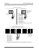
1 Introduction About TransTalk® 9000 Products The following illustrations show which phone models and carriers can be used together: Single Carrier Installation If you have a Model 117A1 Carrier... Use only... If you have a Model 117A3 Carrier, or Model 117A4 Carrier... You can use...
About the MDW 9031/9031DCP Pocket Phone Introduction 1 About the MDW 9031/9031DCP Pocket Phone The MDW 9031/9031DCP Pocket Phone is not only wireless, but it is also lightweight and pocket-sized. A removable carrying clip and a lanyard are provided with the handset. You can use either the clip or the lanyard for hands-free portability. The MDW 9031/9031DCP also has a headset connector to accommodate an optional headset.
1 Introduction About the MDW 9031/9031DCP Pocket Phone Parts List Along with this book and the MDW 9031/9031DCP Pocket Phone Quick Reference, the box should contain the items shown below. If it does not, call for customer support as described in the Copyright and Legal Notices at the beginning of this book.
Introduction 1 About the MDW 9031/9031DCP Pocket Phone Additional Parts The following parts may be necessary, depending upon your installation. This Kit of Parts is required only when a single (stand-alone) MDW 9031/9031DCP Pocket Phone is installed: Rubber Feet (4) Radio Module 11-foot (3.
1 Introduction About the MDW 9031/9031DCP Pocket Phone Spare Battery and Headset One nickel metal hydride battery pack, which provides up to 3 hours of talk time, comes with your MDW 9031/9031DCP Pocket Phone. For extended phone usage, you should purchase an additional battery pack. If you require full business-day use, you can purchase an extended battery pack. Although thicker and heavier than the standard battery pack, the extended battery pack provides 8-9 hours of talk time when fully charged.
2 Installing the MDW 9031/9031DCP Pocket Phone Important Safety Instructions This book contains instructions related to safety labels on the product: ! WARNING: WARNING indicates the presence of a hazard that can cause severe or fatal personal injury if the hazard is not avoided. ! CAUTION: CAUTION indicates the presence of a hazard that will or can cause minor personal injury or property damage if not avoided.
2 Installing the MDW 9031/9031DCP Pocket Phone Cardiac Pacemakers Important Safety Instructions ! CAUTION: The MDW 9031/9031DCP handset is a radio device and, like all radio devices, should not be placed next to a pacemaker. Preliminary studies performed at the US Food and Drug Administration (FDA) and elsewhere have shown that when digital cellular telephones are placed very close to implanted cardiac pacemakers, interference with the operation of the implanted pacemaker can occur.
Important Safety Instructions Installing the MDW 9031/9031DCP Pocket Phone 2 • Read and understand all instructions in this book before using this product. • Observe all warnings and instructions marked on the product. • Do not use the product near water or when you are wet. If the product comes in contact with any liquids, unplug the power cord and telephone line cords immediately. Do not plug the product back in until it has dried thoroughly.
2 Installing the MDW 9031/9031DCP Pocket Phone Important Safety Instructions ! WARNING: The rechargeable battery pack may contain elements that are harmful to the environment (for example, nickel). Do not burn or puncture the battery pack. As with other batteries of this type, burning or puncturing could release toxic material which could cause injury. Do not dispose of the battery pack in household garbage.
Installing the MDW 9031/9031DCP Pocket Phone 2 Important Safety Instructions • This product uses a 3-prong plug. Such plugs are designed for your safety. Do not attempt to defeat this purpose. If your wall outlet will not accept the plug, the outlet should be replaced by an electrician. ! WARNING: Failure to properly ground this product will result in a risk of electrical shock, which can cause serious personal injury. This product requires a 3-prong AC outlet for safe operation.
2 Installing the MDW 9031/9031DCP Pocket Phone Installation Overview for Radio Modules Installation Overview for Radio Modules and Carriers This section explains how to install radio modules and carriers.
Installation Overview for Radio Modules and Carriers Installing the MDW 9031/9031DCP Pocket Key Components Each radio module communicates with a corresponding handset. The matching sets are identified by a serial number located on the bottom of the radio module and in the battery compartment of the handset.
2 Installing the MDW 9031/9031DCP Pocket Phone Radio Module Mounting Rods Installation Overview for Radio Modules T RANS TALK Wall Mount Hole Wall Mount Hole Label with Model Number (not shown) Power Cord Connector (not shown) CAUT IN Jack OUT Jack OUT OF SYNC LED CONTROL/EXPANSION LED (Model 117A4 Only) ION ONLY USECABLE AT&T 667896 847 P⁄N IN OUT NC OF SY OUT NTROL/ CO NSION EXPA Card Edge Connectors Slot Numbers 1 2 3 4 5 6 Wall Mount Hole Wall Mount Hole Cable Manager Slot Rear E
Installation Overview for Radio Modules and Carriers Installing the MDW 9031/9031DCP Pocket Positioning a Radio Module or Carrier(s) Each of your handsets and its corresponding radio module operates within a single zone of coverage: Approximately 500 to 900 feet in a typical office building; up to 1200 feet in an unobstructed environment POWER RADIO PASS Single Radio Module, Single Carrier, or Multiple Carriers The range depends on your particular operating environment.
2 Installing the MDW 9031/9031DCP Pocket Phone Additional Rules for Installing a Single Radio Module Only Installation Overview for Radio Modules • Never install the radio module or carrier(s) above a drop, suspended ceiling. • Do not locate the radio module or carrier(s) within 3 feet (0.9 m) of any large metal object, and be sure no metal objects are in the line of sight to the operating area of the handset. • Do not locate the radio module or carrier(s) within 6 feet (1.
Installing the MDW 9031/9031DCP Pocket Phone 2 Installing a Single Radio Module Additional Rules for Installing One or More Carriers • Install carrier(s) within 15 feet (5 m) of either side of, and within 6 to 8 feet (1.8 to 2.4 m) above, a properly grounded, 3-prong electrical outlet that is not controlled by an on/off switch. • Choose a location where handset users will not approach the carrier(s) within a radius of 6 feet (1.8 m) for 1 or 2 carriers or 10 feet (3 m) for 3 carriers.
2 Installing the MDW 9031/9031DCP Pocket Phone Installing a Single Radio Module 3 Detach the rubber feet from the shipping card. Apply them to marked areas on the underside of the radio module. 4 Place the wall-mounting plate against the wall. Choose a location backed by a wooden stud (if unavailable, use toggle bolts instead of the supplied wood screws). Lightly tap a nail into the wall to start holes. Then screw the plate flush to the wall.
Installing the MDW 9031/9031DCP Pocket Phone 2 Installing a Single Radio Module 5 Insert one end of the telephone line cord into an extension jack or terminal/station connector on your communications system switch/control unit (refer to your communications system manual for the proper location).
2 Installing the MDW 9031/9031DCP Pocket Phone Installing a Single Radio Module 7 Plug the power cord/AC adapter into a properly grounded, 3-prong wall outlet that is not controlled by an on/off switch. ! CAUTION: Never connect or disconnect the telephone line cord while the radio module is plugged into the wall outlet. Single Radio Module Installation Self-Test Verify that the POWER and PASS LEDs on the radio module light.
Installing the MDW 9031/9031DCP Pocket Phone 2 Understanding Carriers Note: The RADIO LED also may light upon installation; however, since the RADIO LED has no significance during installation, ignore its operation. The RADIO LED indicates a connection between the handset and the radio module; it lights when the handset is being used as long as the battery pack in the handset is charged.
2 Installing the MDW 9031/9031DCP Pocket Phone Understanding Carriers As the following illustration shows, each Model 117A3 carrier has two user-adjustable DIP switches—one in Slot 2 that controls the power levels, and another in Slot 4 that specifies whether this particular carrier is functioning as a control or an expansion carrier.
Installing the MDW 9031/9031DCP Pocket Phone 2 Understanding Carriers 2 2 O N 1 O N 1 O N If your MDW 9031/9031DCP Pocket Phones are interfering with other wireless products in use or if you anticipate that they will, you can adjust the carrier’s range by setting each 117A3 carrier’s power DIP switch, located in Slot 2.
2 Installing the MDW 9031/9031DCP Pocket Phone Understanding Carriers Use a nonmetallic, pointed object to set each 117A3 carrier’s DIP switch according to the following table. Note: You must set the DIP switch for all of the 117A3 carriers to the same setting.
Installing the MDW 9031/9031DCP Pocket Phone 2 Understanding Carriers 2 2 O N 1 O N 1 O N The Model 117A3 carrier can serve as either a control or an expansion carrier. Whether you install one or more 117A3 carriers, you must set the Control/Expansion DIP switch in Slot 4 of each 117A3 carrier to indicate which role that carrier is filling.
2 Installing the MDW 9031/9031DCP Pocket Phone Understanding Carriers Use a nonmetallic, pointed object to set each 117A3 carrier’s DIP switch according to the following table. Note: Only one carrier (the leftmost carrier) can be the control carrier; the other carriers must be expansion carriers. To designate the carrier as a... Use this setting for the DIP switch...
Installing the MDW 9031/9031DCP Pocket Phone 2 Understanding Carriers Understanding Your Model 117A4 Carrier The Model 117A4 carrier differs from the 117A3 in that it does not require that Slot 6 contain a radio module in order to pass the signal from the control carrier to the next carrier. It also does not have Power and Control/Expansion DIP switches to set. The 117A4 automatically adjusts its power level and senses whether it is being used as a control or an expansion carrier.
2 Installing the MDW 9031/9031DCP Pocket Phone Understanding Carriers The following chart explains the label that identifies the jacks and LEDs on the 117A4 carrier. (The IN and OUT jacks and the OUT OF SYNC LED also appear on the 117A3 carrier.) Label Explanation IN Designates the modular jack that accepts the modular plug and cable from the preceding carrier to the left. If the jack is in use, this carrier is an “expansion” carrier.
Understanding Carriers Installing the MDW 9031/9031DCP Pocket Phone 2 The label at the top of the right side of the carrier is provided to help you interpret the LED lights. The first three lines on this label refer to LEDs on the control carrier, the next three lines refer to the LEDs on each of the expansion carriers, and the last two lines apply to all carriers. Go to either of the following: • If installing a single carrier, go to “Installing a Single Carrier.
2 Installing the MDW 9031/9031DCP Pocket Phone Installing a Single Carrier Installing a Single Carrier If you are installing a Model 117A3 carrier, be sure you have read the following sections and have set the DIP switches: • “Understanding Your Model 117A3 Carrier” • “Setting the 117A3 Carrier Power Level” • “Setting the 117A3 Carrier Control/Expansion DIP Switch” Then go to either of the following: • “Installing a Single Carrier on a Shelf or Desk” • “Installing a Single Carrier on a Wall” If
Installing the MDW 9031/9031DCP Pocket Phone 2 Installing a Single Carrier Installing a Single Carrier on a Shelf or Desk • You will not receive optimum performance if the unit is placed on a desk or low shelf. • Install the unit as high as possible, leaving 6 to 12 inches (15.2 to 30.5 cm) between the top of the antenna and the ceiling, if on a high shelf. • Never install or remove a radio module from a carrier that is plugged into a wall outlet (hot insertion).
2 Installing the MDW 9031/9031DCP Pocket Phone Installing a Single Carrier 4 Starting from the leftmost slot (#1), insert each radio module into the carrier by hooking it onto the radio module mounting rod. Slowly swing the radio module’s card edge into the card edge connector on the back of the carrier. 5 When the card edge is fully seated, a snap lock on the bottom of the radio module will engage.
Installing a Single Carrier Installing the MDW 9031/9031DCP Pocket Phone 2 6 Insert a telephone line cord into the bottom of each radio module. 7 Slide the telephone line cords through the rear exit slots on the bottom of the carrier. Cords originating from Modules 1 and 6 can share exit slots with cords from Modules 2 and 5, respectively.
2 Installing the MDW 9031/9031DCP Pocket Phone Installing a Single Carrier 8 Insert the free end of the telephone line cord into the appropriate extension jack or terminal/station connector on your communications system switch/control unit (refer to your communications system manual for the proper location).
Installing a Single Carrier Installing the MDW 9031/9031DCP Pocket Phone 2 10 Place the carrier on its feet towards the back of the shelf or desk, making sure it is in a stable position. Be sure the telephone line cords come out the rear exit slots in the back of the unit. Arrange the power cord and telephone line cords beneath the shelf or desk, so no one can step on them or trip over them.
2 Installing the MDW 9031/9031DCP Pocket Phone Installing a Single Carrier Installing a Single Carrier on a Wall • Install the unit high on a wall, leaving 6 to 12 inches (15.2 to 30.5 cm) between the top of the antenna and the ceiling. • Never install or remove a radio module from a carrier that is plugged into a wall outlet (hot insertion). • See “Key Components” earlier in this chapter for additional picture detail.
Installing the MDW 9031/9031DCP Pocket Phone 2 Installing a Single Carrier 4 Remove the plastic cap covering each radio module’s card edge before inserting the radio modules into the carrier. 5 Starting from the leftmost slot (#1), insert each radio module into the carrier by hooking it onto the radio module mounting rod. Slowly swing the radio module’s card edge into the card edge connector on the back of the carrier.
2 Installing the MDW 9031/9031DCP Pocket Phone Installing a Single Carrier 7 Insert a telephone line cord into the bottom of each radio module. 8 Slide the telephone line cords through the cable manager slot on the left front of the carrier. 9 Insert the free end of each telephone line cord into the appropriate extension jack or terminal/station connector on your communications system switch/control unit (refer to your communications system manual for the proper location).
Installing the MDW 9031/9031DCP Pocket Phone 2 Installing a Single Carrier 10 Plug the carrier’s AC adapter cord into the left side of the carrier. 1 2 3 4 5 11 Insert the carrier’s power cord into the AC adapter, then plug the power cord into a properly grounded, 3-prong wall outlet that is not controlled by an on/off switch. If appropriate, you can wall-mount the AC adapter using its attached wallmounting bracket.
2 Installing the MDW 9031/9031DCP Pocket Phone Installing a Single Carrier Single Carrier Installation Self-Test To perform a single carrier self-test: 1 A single carrier must always function as a control carrier. Wait a few seconds, then check the LED(s) on the right side of the carrier: ~ Model 117A4: Compare the OUT OF SYNC and CONTROL/EXPANSION LEDs against the top three lines on the “SYNC and CONTROL/EXP LED Codes” label. ~ Model 117A3: The 117A3 has no CONTROL/EXPANSION LED.
Installing the MDW 9031/9031DCP Pocket Phone 2 Installing Multiple Carriers 3 If you are using a Model 117A4 carrier, verify that the carrier’s CONTROL/EXPANSION LED is lit and that its color is green. This is correct for a single-carrier installation. 4 Verify that the POWER and PASS LEDs on each radio module are lit. If a radio module’s PASS LED does not light, power down the carrier and the module, wait 15 seconds, and repower the module and then the carrier.
2 Installing the MDW 9031/9031DCP Pocket Phone Installing Multiple Carriers Multiple-carrier installation involves several stages: • Mounting the carriers on the wall and cabling them. • Installing a single radio module in each carrier. • Installing the remaining radio modules. The most efficient method for installing carriers and their radio modules is to perform self-tests after each stage of the installation.
Installing the MDW 9031/9031DCP Pocket Phone 2 Installing Multiple Carriers 4 Place the carrier assembly over the screws, then slide it downward to lock it into place. Be sure that the leftmost carrier is the control carrier. Tighten the screws. Repeat for each carrier. 5 Connect an expansion cable to the OUT jack of the control carrier.
2 Installing the MDW 9031/9031DCP Pocket Phone Installing Multiple Carriers 8 Plug an AC adapter cord into the left side of each carrier. 1 2 3 4 5 9 Insert each carrier’s power cord into its AC adapter. If appropriate, you can wall-mount each AC adapter using its attached wallmounting bracket.
Installing the MDW 9031/9031DCP Pocket Phone 2 Installing Multiple Carriers 10 Plug each carrier’s power cord into one of the following power sources that is not controlled by an on/off switch: ~ Surge-suppressor strip. ~ Properly grounded, 3-prong wall outlets. (See “wall outlets” in the following chart for the order in which to power up the carriers.) 11 Power the carriers as follows: If the carriers are plugged into... Then... one surge suppressor strip Power the strip.
2 Installing the MDW 9031/9031DCP Pocket Phone Installing Multiple Carriers Multiple Carrier Mounting and Cabling Self-Test To perform a multiple carrier mounting and cabling self-test: 1 Wait a few seconds after powering up the carriers, then verify that the red OUT OF SYNC LEDs on all carriers are lit. This is normal when no radio modules have yet been installed.
Installing Multiple Carriers Installing the MDW 9031/9031DCP Pocket Phone 2 3 At this stage of your installation, verify the LEDs displayed match the third of the SYNC and CONTROL/EXP LED Codes label, depending on whether the carrier is the control or an expansion carrier. 4 If the LEDs on your installation do not reflect this pattern, there is probably a mistake in the cabling.
2 Installing the MDW 9031/9031DCP Pocket Phone Installing Multiple Carriers Installing a Single Radio Module in Each Carrier To install a single radio module in each carrier: 1 Power down the carriers. 2 Remove the plastic cap covering each radio module’s card edge before inserting the radio modules into the carriers. 3 Working from left to right, insert a radio module into the first slot (Slot 1) of each carrier; hook each radio module onto the mounting rod.
Installing Multiple Carriers Installing the MDW 9031/9031DCP Pocket Phone 2 4 When the card edge is fully seated, a snap lock on the bottom of the radio module will engage. 5 Insert a telephone line cord into the bottom of each radio module. 6 Slide the telephone line cords through the cable manager slot on the left front of each carrier.
2 Installing the MDW 9031/9031DCP Pocket Phone Installing Multiple Carriers 7 Insert the free end of each telephone line cord into the appropriate extension jack or terminal/station connector on your communications system switch/control unit (refer to your communications system manual for the proper location).
Installing the MDW 9031/9031DCP Pocket Phone 2 Installing Multiple Carriers Installation Self-Test with a Single Radio Module in Each Carrier To perform an installation self-test with a single radio module in each carrier: 1 Wait a few seconds after powering up the carriers, then verify that the carriers’ OUT OF SYNC LEDs are not lit. 2 The following illustration shows the correct LED lights for a five-carrier installation with one radio module installed in each carrier.
2 Installing the MDW 9031/9031DCP Pocket Phone Installing Multiple Carriers 3 At this stage of your installation, verify that the LEDs displayed match the first or fourth lines of the SYNC and CONTROL/EXP LED Codes label. 4 If an OUT OF SYNC LED is lit, power down, wait at least 15 seconds, and then repower the carriers in order from left to right, as described in Step 8 in “Installing a Single Radio Module in Each Carrier.
Installing the MDW 9031/9031DCP Pocket Phone 2 Installing Multiple Carriers 5 The PASS and POWER LEDs on all radio modules should be lit and green. If a radio module’s PASS LED is not lit: a Power down the carriers. b From the wall outlet, unplug the power cord/AC adapter of the radio module that did not light. c Wait 15 seconds. d Plug in the radio module’s power cord again. e Repower the carriers, following the proper left-to-right order.
2 Installing the MDW 9031/9031DCP Pocket Phone Installing Multiple Carriers Installing the Remaining Radio Modules To install the remaining radio modules: 1 Power down the carriers. 2 Remove the plastic cap covering each radio module’s card edge before inserting the radio modules into the carriers. 3 Beginning with the first empty slot and working from left to right, insert a radio module into each slot of the control carrier. Hook each radio module onto a mounting rod.
Installing the MDW 9031/9031DCP Pocket Phone 2 Installing Multiple Carriers 4 When the card edge is fully seated, a snap lock on the bottom of the radio module will engage. 5 Repeat Steps 3 and 4 for each expansion carrier, until each radio module is inserted into a carrier. Note: Fill all six slots of the current carrier before inserting radio modules into the next carrier. 6 Insert a telephone line cord into the bottom of each radio module.
2 Installing the MDW 9031/9031DCP Pocket Phone Installing Multiple Carriers 7 Slide the telephone line cords through the cable manager slot on the left front of the carrier. 8 Insert the free end of each telephone line cord into the appropriate extension jack or terminal/station connector on your communications system switch/control unit (refer to your communications system manual for the proper location).
Installing the MDW 9031/9031DCP Pocket Phone 2 Installing Multiple Carriers 9 Power the carriers as follows: If the carriers are plugged into... Then... one surge suppressor strip Power the strip. Result: All the carriers will turn on simultaneously.
2 Installing the MDW 9031/9031DCP Pocket Phone Installing Multiple Carriers Installation Self-Test for Remaining Radio Modules To perform an installation self-test for the remaining radio modules: 1 Wait a few seconds after powering up the carriers, then verify that the carriers’ OUT OF SYNC LEDs are not lit.
Installing the MDW 9031/9031DCP Pocket Phone 2 Installing Multiple Carriers 3 If an OUT OF SYNC LED is lit, power down, wait at least 15 seconds, and then repower the carriers in order from left to right, as described in Step 9 in “Installing the Remaining Radio Modules.” If the LED is still lit, follow the suggestions in the “Installation Problems” section of Chapter 5, “Troubleshooting.
2 Installing the MDW 9031/9031DCP Pocket Phone Handset Handset This section explains how to install the handset battery pack, change the communications system setting, and fill out the handset label. Inserting and Removing the Handset’s Battery Pack To insert and remove the battery pack: 1 To insert the battery pack into the handset, insert the two small rectangular tabs located along the bottom back edge of the handset into the two rectangular holes along the bottom front edge of the battery pack.
Handset Installing the MDW 9031/9031DCP Pocket Phone 2 3 To remove the battery pack, slide the spring latch upward (away from the battery pack). While holding the latch up, grasp both sides of the battery pack, then gently pull the battery pack upward and out. Changing the Communications System Setting The communications system you use determines what information the MDW 9031/9031DCP Pocket Phone can display and how the phone lines and programmable/intercom/drop buttons are identified.
2 Installing the MDW 9031/9031DCP Pocket Phone Handset 4 Press and hold “M” (6) for three seconds to enter Button Mapping Mode. The handset display shows one of the following: MAP:P PARTNER Systems MAP:D DEFINITY Systems, System 25, System 75, and System 85 Note: The MDW 9031DCP should only be set to MAP:D for DEFINITY.
Installing the MDW 9031/9031DCP Pocket Phone 2 Handset Filling Out the Handset Label MDW 9031/9031DCP Pocket Phone display shows the status of up to 12 lines or programmable/intercom/drop buttons. Since the MDW 9031/9031DCP is compatible with several different communications systems, diagrams of the button mappings for these systems are provided in Chapter 6. Note: The MDW 9031DCP is compatible only with DEFINITY.
2 Installing the MDW 9031/9031DCP Pocket Phone Battery Charger Battery Charger This section explains how to choose a location for the battery charger and install it. It also explains how to insert and remove a battery pack. Positioning the Battery Charger The battery charger can be placed on a desk, or it can be mounted on a wall. Before you install the battery charger, note the following considerations: • Locate the battery charger within 5 feet (1.
Battery Charger Installing the MDW 9031/9031DCP Pocket Phone 2 5 Insert the battery charger’s power cord/AC adapter into the battery charger. If you are desk-mounting the battery charger, skip to Step 7. 6 Place the keyhole-shaped openings in the back of the battery charger over the screw heads and wall spacers, then slide the battery charger downward into the groove in the wall spacers to lock it into place.
2 Installing the MDW 9031/9031DCP Pocket Phone Battery Charger Inserting a Battery Pack into the Spare Battery Compartment Slide the battery pack (or an optional extended battery pack) into the spare battery compartment until it is firmly seated with the back of the battery pack against the back of the spare battery compartment. Do not force the battery pack down. The battery pack should slide easily into the slot.
Battery Charger Installing the MDW 9031/9031DCP Pocket Phone 2 The extended battery pack slides down into the spare battery compartment. Extended Spare Battery Pack Handset Cradle Spare Battery Pack Guide Pin Battery Charger Contacts Spare Battery Compartment SPARE LED Removing a Battery Pack from the Spare Battery Compartment To remove a battery pack from the spare battery compartment of the charger, lift the battery pack up and out.
2 Installing the MDW 9031/9031DCP Pocket Phone Battery Charger Inserting the Handset into the Battery Charger’s Handset Cradle Correct positioning of the handset in the charger is important to ensure proper charging: 1 Position the handset (with either battery pack attached) so that the two small round holes in the bottom of the handset fit over the two guide pins on the bottom of the handset cradle.
3 Using the MDW 9031/9031DCP Pocket Phone Important Safety Instructions Please see “Important Safety Instructions” at the beginning of Chapter 2. Handset The MDW 9031/9031DCP Pocket Phone supports normal operation of all of the features of the switch as far as is practical within the limitations of its reduced size and power and the nature of wireless operation. There are very few differences in operation between the wireless MDW 9031/9031DCP Pocket Phone and a wired deskset.
3 Using the MDW 9031/9031DCP Pocket Phone Handset Handset Controls Receiver Receives the sound of your caller’s voice, unless a headset is connected. Headset On/Off Press to turn the headset on if the headset is plugged in. ON appears in handset display. To turn off, press again. Turn on to make or answer a call, and turn off to “hang up.” Antenna Extend fully or retract fully to use handset. Extend fully to maximize the handset range and voice quality.
Using the MDW 9031/9031DCP Pocket Phone 3 Handset Column and Select Buttons The MDW 9031/9031DCP Pocket Phone can display the status of up to 10 lines/intercom/programmable buttons, but the number of lines supported by compatible communications system switches varies. However, it has only 4 selection buttons (the Column buttons). The Select button ( " ) is used in conjunction with the Column buttons ( '’ ) to increase the available selections to 12.
3 Using the MDW 9031/9031DCP Pocket Phone Handset Handset Display (with Backlighting) The MDW 9031/9031DCP Pocket Phone display has one 16-alphanumeric-character line and four lines of icons to provide you with status information. The display provides Backlighting (a programmable option) either when the handset is turned on or when the " button is pressed. See “Changing the Handset Setting.”later in this chapter.
Using the MDW 9031/9031DCP Pocket Phone 3 Handset When the display is blank, the handset is either turned off or in the power-saving “sleep” mode. You can activate the display and Backlighting (if programmed) by pressing O, turning the handset on, or by pressing " to “wake it up.
3 Using the MDW 9031/9031DCP Pocket Phone Line Status Indicators Handset There are 12 status indicators; each one corresponds to a specific outside line or programmable/intercom/drop button. (The function of these status indicators varies, depending on the communications system you are using—see the Button Mapping topic for the appropriate communications system switch in Chapter 6, “MDW 9031/9031DCP Pocket Phone Compatibility.
Using the MDW 9031/9031DCP Pocket Phone 3 Handset Low Battery Indicator The standard battery pack has approximately three hours of continuous talk time after being fully charged. The optional extended battery pack has approximately eight hours of continuous talk time after being fully charged. When the handset is On and the battery power is low, the handset will emit two beeps and the Battery icon in the handset display will flash. When this occurs, you have five minutes or less of talk time left.
3 Using the MDW 9031/9031DCP Pocket Phone Attaching the Metal Carrying Clips Handset To attach the metal carrying clip to the battery pack, do the following: 1 Remove the battery pack from the handset, as described in “Inserting and Removing the Handset's Battery Pack” in Chapter 2. Standard Spare Battery Pack Extended Spare Battery Pack 2 Place the two metal tabs on the clip into the slots on the battery pack, with the “hooks” toward the bottom of the battery pack.
Using the MDW 9031/9031DCP Pocket Phone 3 Handset Standard Spare Battery Pack Extended Spare Battery Pack 4 Latch the right edge of the clip into the corresponding groove on the inner side of the battery pack. 5 Push the left edge of the belt clip and snap it into the corresponding groove on the inner side of the battery pack. 6 Reinsert the battery pack in the handset, as described in “Inserting and Removing the Handset’s Battery Pack” in Chapter 2.
3 Using the MDW 9031/9031DCP Pocket Phone • Line Preselection • Backlighting • Alerter Handset Local Mode also gives you access to Local Test Mode (which enables you to test the alerter, vibrator, and display) and Wireless Test Mode (which enables you to test sound clarity, signal strength, and voice quality). While in Local Mode, the MDW 9031/9031DCP can still receive notification of incoming calls. To access Local Mode, use the following procedure: 1 Make sure the handset is turned off.
Using the MDW 9031/9031DCP Pocket Phone 3 Handset 3 While still holding ", press O. The handset beeps twice, and the display shows the handset settings, indicating that you are now in Local Mode. (While in Local Mode, the MDW 9031/9031DCP can still receive notification of incoming calls.) If the vibrator is enabled, the VIBR icon appears in the display. For example: ON If the vibrator is disabled, no icon appears. 4 Press “V” (8) on the dialpad to enable or disable the vibrator.
3 Using the MDW 9031/9031DCP Pocket Phone Handset 3 While still holding ", press O. The handset beeps twice, and the display shows the handset settings, indicating you are in Local Mode. (While in Local Mode, the MDW 9031/9031DCP can still receive notification of incoming calls.) If Line Preselection is enabled, PSEL appears on the top line of the display. For example: If Line Preselection is disabled, no icon appears. 4 Press and hold “P” (7) for three seconds.
Using the MDW 9031/9031DCP Pocket Phone 3 Handset Enabling or Disabling the Alerter The alerter is an audible signal to notify you of an incoming call. If a call comes in while the phone is idle, the handset rings. If you are already on a call, the handset chirps softly. You can adjust the volume of the alerter by pressing the “+” button or the “-” button on the side of the handset when the phone is turned off.
3 Using the MDW 9031/9031DCP Pocket Phone Handset Test Modes You can use Local Test Mode and Wireless Test Mode to verify that your handset is working properly and that the MDW 9031/9031DCP System is performing optimally.
Using the MDW 9031/9031DCP Pocket Phone 3 Handset Using Wireless Test Mode You can determine sound clarity, signal strength, and voice quality using Wireless Test Mode. You should use Wireless Test Mode to help you locate the best place to install the radio module(s) to optimize the performance of your MDW 9031/9031DCP Pocket Phone. Repeat the tests several times, with the radio module positioned in a different location each time.
3 Using the MDW 9031/9031DCP Pocket Phone Handset 6 To determine sound clarity, listen to the simulated dial tone as you walk around. A clear, steady tone indicates good sound clarity. 7 To determine signal strength, press 1.
Using the MDW 9031/9031DCP Pocket Phone 3 Handset The higher the number, the better the voice quality, as shown in the table below. A low number may indicate potential interfering devices (such as another radio transmitter) in the area. You can press 2 again to show a subsequent voicequality reading. Each time you press 2, you get a new reading.
3 Using the MDW 9031/9031DCP Pocket Phone Handset Close Up Test At no more than 5 to 10 feet (1.5 to 3.1 m) from its radio module, use the following procedure: 1 Make sure the handset is turned off. 2 Press and hold the Select button ( " ) for three seconds. 3 While still holding ", press O. The handset beeps twice, and the display shows the handset settings, indicating you are in Local Mode. (While in Local Mode, the MDW 9031/9031DCP can still receive notification of incoming calls.
Using the MDW 9031/9031DCP Pocket Phone 3 Handset 2 With a signal strength of 3, press 2 to check the voice quality. When the voice quality is 7 or 8, the voice connection should be satisfactory. This is the edge of your usable range. The following diagram illustrates this Performance/Range test. Close-Up Test 5 to 10 feet (1.5 to 3.
3 Using the MDW 9031/9031DCP Pocket Phone Handset Making a Call To make a call using your MDW 9031/9031DCP, use the following procedure: 1 Press the handset O button (or the headset O button if you have the headset attached) to turn the phone on. ~ The MDW 9031/9031DCP seizes an available line and a truncated triangle or a small rectangle (depending on your communications system) appears around that line in the handset display. ~ You hear a dial tone.
Using the MDW 9031/9031DCP Pocket Phone 3 Handset To deselect the line or button, press O. For information about assigning features to buttons, see “Programming Features for PARTNER, MERLIN, and MERLIN LEGEND Systems” in Chapter 6. Preselecting a Line You may sometimes want to select a line other than the line to which the communications system automatically connects you. To preselect a line, you must first enable Line Preselection. See “Enabling or Disabling Line Preselection” earlier in this chapter.
3 Using the MDW 9031/9031DCP Pocket Phone Handset ! CAUTION: Plug ONLY the Supra 9031 headset cord or the Radium headset cord into the headset adapter. Note: Calls cannot be heard on the handset receiver when the headset is plugged in to the headset adapter. The handset microphone is also deactivated. The range of the handset is slightly diminished when you are using a headset. You may need to move closer to the radio module or move the radio module closer to you.
Using the MDW 9031/9031DCP Pocket Phone 3 Battery Charger Battery Charger The battery charger charges battery packs in the spare battery compartment and in the handset. If both are present at the same time, charging in the spare battery compartment is suspended until the battery pack in the handset is fully charged. To enable extended phone usage, you should purchase an extra battery pack and store it in the charger, so that you always have a charged battery pack to switch to, if necessary.
3 Using the MDW 9031/9031DCP Pocket Phone Battery Charger The color of the battery charger’s LEDs indicates the state of the corresponding battery pack, as shown in the following table: Battery charger LED shows... If it is the SPARE LED, the battery pack in the spare battery compartment... If it is the HANDSET LED, the battery pack in the Handset... If it is the REFRESH LED, the Refresh button was pressed, and the Handset battery pack...
Using the MDW 9031/9031DCP Pocket Phone 3 Battery Charger Note that your handset will consume power both during talk time (when the handset is turned on) and during standby time (when the handset is turned off, but out of the battery charger).
3 Using the MDW 9031/9031DCP Pocket Phone 94 Issue 3 October 1999 Battery Charger MDW 9031/9031DCP Wireless Pocket Phone Installation and Use 503-801-166
4 Maintaining the MDW 9031/9031DCP Pocket Phone Important Safety Instructions Please see “Important Safety Instructions” at the beginning of Chapter 2. Removing Radio Module from Carrier • Slot 6 of a Model 117A3 control carrier must always contain a radio module to pass the synchronization signal to the next carrier. • See “Key Components” in Chapter 2 for additional picture detail. To remove a radio module from the carrier: 1 Unplug the carrier(s) power cord/AC adapter from the wall outlet.
4 Maintaining the MDW 9031/9031DCP Pocket Phone Removing Radio Module from Carrier 2 Unplug the telephone line cord from the bottom of the radio module. 3 Press up and hold the snap lock on the bottom rear of the radio module. 4 Slowly swing the radio module’s card edge out of the card edge connector on the back of the carrier, releasing the snap lock when clear. Unhook the radio module from the radio module mounting rod by gently lifting upward.
Maintaining the MDW 9031/9031DCP Pocket Phone 4 Removing Radio Module from Carrier 5 If you removed a radio module from Slot 6 of an 117A3 control carrier, you must insert another radio module into this slot. Failure to do so will cause the carriers to be unsynchronized. 6 Repower the carrier.
4 Maintaining the MDW 9031/9031DCP Pocket Phone Swapping Extensions Swapping Extensions If you want to change your phone’s extension number assignment, make sure the radio module or carrier(s) is unplugged before you unplug the telephone line cord from the communications system switch/control unit. Power down and then repower the carrier(s) after all extension changes are made. To swap extensions: 1 Unplug the carrier(s) power cord/AC adapter from the wall outlet.
Maintaining the MDW 9031/9031DCP Pocket Phone 4 Swapping Extensions 4 Repower the carrier.
4 Maintaining the MDW 9031/9031DCP Pocket Phone Replacing Antenna Replacing Antenna If the antenna on your MDW 9031/9031DCP Pocket Phone handset becomes damaged, you can order a replacement antenna (see “Ordering Replacement and Optional Parts” later in this chapter), and replace it yourself. To replace the antenna: 1 Fully retract the antenna. 2 Grasping the base of the antenna, unscrew it by turning it counterclockwise.
Ordering Replacement and Optional PartsMaintaining the MDW 9031/9031DCP Pocket Phone 4 Item Lucent Direct 1-800-451-2100 National Parts Sales Center 1-800-222-PART Lanyard NA 407183417 MDW 9031 Pocket Phone Leather Carrying Case 32043A 847877487 MDW 9031 Pocket Phone Leather Carrying Case customized for headset use 32090A 848026092 Battery Charger; includes Power Cord/AC Adapter 3279-3BC 108386921 Power Cord/AC Adapter for Battery Charger [11 foot (3.
4 Maintaining the MDW 9031/9031DCP Pocket Phone 102 Issue 3 October 1999 Ordering Replacement and Optional MDW 9031/9031DCP Wireless Pocket Phone Installation and Use 503-801-166
5 Troubleshooting Procedures If you have a problem with your MDW 9031/9031DCP Pocket Phone, you may be able to solve it by following the procedures included in this chapter. If you cannot resolve the problem, call Customer Support as described in the Copyright and Legal Notices at the beginning of this book.
5 Troubleshooting Procedures Installation Problems Symptom Possible Causes One or more OUT OF SYNC LEDs is lit, radio module PASS LEDs are not lit, or both. Expansion cable is installed in the wrong IN or OUT jack, or it is not fully inserted into the correct jack. 1 Verify that all expansion cables are fully Carriers were not powered in the correct order.
Troubleshooting 5 Procedures Symptom Possible Causes Possible Solutions After you plug the radio module into an electrical outlet, the radio module’s POWER LED lights, but the PASS LED does not light. Radio module is malfunctioning. Replace the radio module. After you plug the carrier into an electrical outlet, the PASS LED of one or more radio modules does not light. Radio modules are out of synchronization. Power down the carrier, wait 15 seconds, and repower it.
5 Troubleshooting Procedures Symptom Possible Causes Possible Solutions LEDs on the carriers were displaying correctly according to the three self tests in “Installing Multiple Carriers” when you installed the carriers and radio modules, but now the LED conditions have changed. Radio module is malfunctioning. Locate the malfunctioning radio module by using the following procedure: 1 Power down all carriers. 2 Remove the rightmost radio module. 3 Wait 15 seconds.
Troubleshooting 5 Procedures Handset Problems Symptom Possible Causes Possible Solutions After you press O, display does not show anything. There is no battery pack in the handset. Insert a battery pack in the handset. Battery pack is not inserted properly in the handset. Reinsert the battery pack in the handset. Battery pack is not charged.
5 Troubleshooting Procedures Symptom Possible Causes Possible Solutions You can hear the party on the other end, but they cannot hear you. MUTE appears in the handset display. M button was pressed inadvertently. Press M again to turn off the mute feature. When placed in the battery charger’s handset cradle, the handset does not turn off. Battery charger is plugged into an electrical outlet controlled by a switch, and the switch is turned off.
Troubleshooting 5 Procedures Battery Problems Symptom Possible Causes Possible Solutions Battery icon appears in the handset display. This is normal operation for the MDW 9031 Pocket Phone. No action is required. Battery icon flashes in the handset display and the handset beeps twice. Battery power is low. You have 5 minutes or less of talk time left. Either: • Complete your call, turn the handset off, and recharge the battery pack.
5 Troubleshooting Procedures Symptom Possible Causes Possible Solutions The SPARE LED in the spare battery charging compartment turns amber instead of red. The battery pack was jostled while in the battery charger. Remove then replace the battery pack in the charger. The power cord does not fit the battery charger. The model 40B battery charger is not compatible with the older model 40A power cord.
Troubleshooting 5 Procedures Voice Quality Problems Symptom Possible Causes Possible Solutions Handset voice quality and range are not as good as they were before. A competing radio device (for example, a wireless bar-code scanner) has been installed in the area. Both products are competing for the same air space and will conflict when both are being used. Place the handset in Wireless Test Mode as described in Chapter 3.
5 Troubleshooting Procedures Symptom Possible Causes (Continued) You have a malfunctioning radio module. Possible Solutions 1 Remove all but one radio module from the carrier. (See “Removing Radio Module from Carrier” in Chapter 4.) 2 Test each radio module individually, verifying that the POWER and PASS LEDs on each radio module lights when the carrier is powered, and that the OUT OF SYNC LED is not lit. 3 If the PASS LED does not light, the radio module is malfunctioning.
Troubleshooting 5 Procedures Symptom Possible Causes Possible Solutions Volume is too low at any setting and there is noise on the line. Handset or radio module is not working properly. Place the handset in Wireless Test Mode and determine the signal strength and voice quality as described in Chapter 3. Use the Close-Up Test described in “Performance/Range Test in Wireless Test Mode” in Chapter 3. Connection between the radio module and the communications system switch/control unit is incorrect.
5 Troubleshooting Procedures Range Problems Symptom Possible Causes Possible solutions Handset voice quality and range are not as good as they were earlier. A competing radio device (for example, a wireless bar-code scanner) has been installed in the area. Both products are competing for the same air space and will conflict when both are being used. Place the handset in Wireless Test Mode as described in Chapter 3.
Troubleshooting 5 Procedures Symptom Possible Causes (Continued) You have a malfunctioning radio module. Possible solutions 1 Remove all but one radio module from the carrier. (See “Removing Radio Module from Carrier” in Chapter 4.) 2 Test each radio module individually, verifying that the POWER and PASS LEDs on each radio module light when the carrier is powered, and that the OUT OF SYNC LED is not lit. 3 If the PASS LED does not light, the radio module is malfunctioning.
5 Troubleshooting Procedures Symptom Possible Causes Possible solutions No ring on an incoming call. Handset is out of range of its matching radio module. Move the handset closer to the radio module. • Station wiring is incorrect. • Radio module station wiring is not connected to the switch. Check your station wiring, referring to the table in “Radio Module/Switch Wiring” in Chapter 2, and your switch manual’s station port wiring configuration.
Troubleshooting 5 Procedures Battery Charger Problems Symptoms Possible Causes Possible Solutions No LEDs on battery charger light. Battery charger is plugged into an electrical outlet controlled by a switch and the switch is turned off. Plug the battery charger into an outlet not controlled by a switch. HANDSET LED on battery charger does not light when handset is placed in battery charger. Handset is not seated properly in battery charger’s handset cradle.
5 Troubleshooting Procedures Symptoms Possible Causes Possible Solutions HANDSET LED flashes red. Battery pack is defective. If you have a battery pack in the handset and one in the spare battery compartment, remove both battery packs from the charger to clear the red flashing LED. Then test each battery pack separately as follows: 1 Place the battery pack in the battery charger’s spare battery compartment. 2 Wait one minute. If the SPARE LED flashes red, order a new battery pack.
Troubleshooting 5 Procedures Symptoms Possible Causes Possible Solutions SPARE LED on battery charger flashes red. Battery pack is defective. If you have a battery pack in the handset and one in the spare battery compartment, remove both battery packs from the charger to clear the red flashing LED. Then test each battery pack separately as follows: 1 Insert the battery pack in the handset and place the handset in the battery charger’s handset cradle. 2 Wait one minute.
5 Troubleshooting 120 Issue 3 October 1999 Procedures MDW 9031/9031DCP Wireless Pocket Phone Installation and Use 503-801-166
6 MDW 9031/9031DCP Pocket Phone Compatibility Overview This chapter provides compatibility information for your Pocket Phone. 9031 Compatibility If you are using an MDW 9031 Pocket Phone, go to the “MDW 9031 Compatibility” section for compatibility information. 9031DCP Compatibility If you are using an MDW 9031DCP Pocket Phone, go to the “MDW 9031DCP Compatibility” section for compatibility information.
6 MDW 9031/9031DCP Pocket Phone Compatibility MDW 9031 Compatibility For this release... Of this communications system... Use the instructions for a... R1, R2, R3, R4 PARTNER MLS-12D phone* R1, R3, R4, R4.1 PARTNER II (Apparatus code 7311H) R1, R2, R3, R4, R4.
MDW 9031/9031DCP Pocket Phone Compatibility 6 MDW 9031 Compatibility Programming Features for PARTNER, MERLIN, and MERLIN LEGEND Systems On all PARTNER, MERLIN, and MERLIN LEGEND systems, you can assign a feature to an available button (a button that does not have a line or another feature assigned to it): 1 To enter programming mode, turn on the handset, press i, then press / followed by 0 0.
6 MDW 9031/9031DCP Pocket Phone Compatibility MDW 9031 Compatibility PARTNER Systems Button Mapping for PARTNER Systems On PARTNER Systems, the MDW 9031 emulates an MLS-12D telephone. The following diagram illustrates the button assignments on an MLS-12D phone and the corresponding assignments on the MDW 9031 Pocket Phone. MLS-12D 09/10 TUE 10:24a 5 C D 5 6 1 2 Intercom Intercom A B 7 8 3 4 Ext.
MDW 9031/9031DCP Pocket Phone Compatibility 6 MDW 9031 Compatibility Setting the Line Ringing Options for PARTNER Systems Use the following guidelines to ensure optimal voice quality when using MDW 9031 Pocket Phones with a PARTNER, PARTNER Plus, PARTNER II, or PARTNER Advanced Communications System in key mode: Note: Telephone Communications System For PARTNER II hybrid systems that use pooled lines, set the Line Ringing options as described in the following table if more than six MDW 9031 Pocket Phon
6 MDW 9031/9031DCP Pocket Phone Compatibility • To program the Ringing Option feature, use the “triangle” and “rectangle” indicators in the display as the equivalent of red and green LEDs, respectively. • For MERLIN II System users, if you program an Auto Intercom button, idle line preference must be set to intercom. • If any of your incoming lines has the call waiting feature, use the Recall feature (letter “C” in the display) and press it before you pick up a waiting call.
MDW 9031/9031DCP Pocket Phone Compatibility 6 MDW 9031 Compatibility Button Mapping for On all MERLIN Systems, the MDW 9031 emulates a Model BIS-22D phone MERLIN Systems (Apparatus Code 7315H). The BIS-22D button assignments, however, differ except MERLIN 410 and depending on the MERLIN System used. The following diagram illustrates the BISMERLIN 820 22D button assignments and the corresponding assignments on the MDW 9031 for all MERLIN Systems except MERLIN 410 and MERLIN 820.
6 MDW 9031/9031DCP Pocket Phone Compatibility MDW 9031 Compatibility The following diagram illustrates the button assignments on a BIS-22D phone used for MERLIN 410 and 820 Systems and the corresponding assignments on the MDW 9031 Pocket Phone. (See the previous section for button mapping for all other MERLIN Systems, including MERLIN LEGEND Systems).
MDW 9031/9031DCP Pocket Phone Compatibility 6 MDW 9031 Compatibility Setting the Line Ringing Options for MERLIN Systems Use the following guidelines to ensure optimal voice quality when using MDW 9031 Pocket Phones with MERLIN, MERLIN Plus, and MERLIN II: Telephone Communications System TransTalk 9000 System with TransTalk 9000 System with Three Two Carriers (one control and Carriers (one control and two one expansion carrier) expansion carriers) 1 Set Line Ringing for each MERLIN extension that has
6 MDW 9031/9031DCP Pocket Phone Compatibility MDW 9031 Compatibility Consult your System Administration manuals for this compatibility. If your system does not support the items above, consult the System Administration manual for the BIS-10 phone (Apparatus Code 7303S).
MDW 9031/9031DCP Pocket Phone Compatibility 6 MDW 9031 Compatibility ~ If you are programming numbers for the Station Speed Dial feature, dial the numbers to be stored and then dial the Personal Speed Dialing code (#20 through #39), including the #. Listen for a confirmation tone followed by a dial tone. ~ It is recommended that you do not use features that require visuals to be updated while the set is turned off.
6 MDW 9031/9031DCP Pocket Phone Compatibility MDW 9031 Compatibility The 7315H phones are programmed for DEFINITY systems using four STATION Administration screens. Enter 7315H in the Type field on the first screen to bring up the following two screens.
MDW 9031/9031DCP Pocket Phone Compatibility 6 MDW 9031 Compatibility The following illustrations show in parentheses the MDW 9031 Pocket Phone button assignments on Pages 3 and 4 of the STATION Administration screens. The button labeled D on the MDW 9031 Pocket Phone display automatically defaults to the button labeled D (Drop) on the 7315H phones.
6 MDW 9031/9031DCP Pocket Phone Compatibility MDW 9031 Compatibility If your users do not need these features, assign them to “nonappearing” MDW 9031 Pocket Phone buttons; the buttons represented by the numbers 1 through 8 on the Pocket Phone display can then be used for features the users want. The Scroll and Display features shown on Page 4 of the STATION Administration screens are assigned to buttons 11 and 12 (which cannot be accessed from MDW 9031 Pocket Phones).
MDW 9031DCP Compatibility MDW 9031/9031DCP Pocket Phone Compatibility 6 MDW 9031DCP Compatibility Programming and Call Handling Instructions The MDW 9031DCP Pocket Phone can display the status of up to 10 lines/intercom/programmable buttons, but the number of lines supported by compatible communications system switches varies.
6 MDW 9031/9031DCP Pocket Phone Compatibility DEFINITY Systems MDW 9031DCP Compatibility This phone must be administered as an 8410D phone for the DEFINITY Systems. The 8410D phones are programmed for DEFINITY Systems using four STATION Administration screens. Enter 8410D in the Type field on the first screen to bring up the following two screens.
MDW 9031/9031DCP Pocket Phone Compatibility 6 MDW 9031DCP Compatibility The following illustrations show in parentheses the MDW 9031DCP Pocket Phone button assignments on Pages 3 and 4 of the STATION Administration screens. The button labeled D on the MDW 9031DCP Pocket Phone display automatically defaults to the button labeled 04 (Drop) on the 8410D phones.
6 MDW 9031/9031DCP Pocket Phone Compatibility Button Mapping for DEFINITY Systems MDW 9031DCP Compatibility On DEFINITY Systems, the MDW 9031DCP should be aliased as an 8410D phone. The following diagram illustrates the 8410D button assignment, and the corresponding assignments on the MDW 9031DCP for DEFINITY systems. Menu Exit Prev Next Feat/P Twice A 3 B 4 C 5 1 6 2 7 212 MSG 5 Button "8" on the 9031DCP is the Scroll button (non-programmable).
MDW 9031/9031DCP Pocket Phone Compatibility 6 MDW 9031DCP Compatibility Setting the Line Ringing Options for DEFINITY Systems Use the following guidelines to ensure optimal voice quality when using MDW 9031DCP Pocket Phones with DEFINITY Systems: Telephone Communications System DEFINITY Systems TransTalk 9000 System with Two Carriers (One Control and One to Four Expansion Carriers) 1 When TransTalk 9031DCP handsets are configured as individual PBX extensions, no Line Ringing options are necessary.
6 MDW 9031/9031DCP Pocket Phone Compatibility 140 Issue 3 October 1999 MDW 9031DCP Compatibility MDW 9031/9031DCP Wireless Pocket Phone Installation and Use 503-801-166
A Warranty and Repair Information Lucent Technologies Limited Warranty and Limitation of Liability Lucent Technologies warrants to you, the customer, that your wireless telephone system will be in good working order on the date Lucent Technologies or its Authorized Dealer delivers or installs the system, whichever is later (“Warranty Date”).
A Warranty and Repair Information Repair Information Limitation of Liability Except as provided below, the liability of Lucent Technologies and its affiliates and suppliers for any claims, losses, damages, or expenses from any cause whatsoever (including acts or omissions of third parties), regardless of the form of action, whether in contract, tort, or otherwise, shall not exceed the lesser of: (1) the direct damages proven; or (2) the repair cost, replacement cost, license fee, annual rental charge, or
B Regulatory Information This appendix contains information about the Federal Communications Commission and Industry Canada. FCC Part 15 Rules The Lucent Technologies MDW 9031/9031DCP Wireless Pocket Phone has been tested and has been found to comply with FCC Part 15 Rules. These specifications are designed to provide reasonable protection against harmful interference in a commercial or residential installation.
B Regulatory Information 144 Issue 3 October 1999 Hearing Aid Compatibility MDW 9031/9031DCP Wireless Pocket Phone Installation and Use 503-801-166
C Specifications GENERAL Model: MDW 9031/9031DCP Wireless Pocket Phone Dimensions and Weights: Handset 6.0"(L) x 1.0"(D) x 2.25"(W) 15.24 x 2.54 x 5.71 cm 0.33 lb 0.15 kg Handset w/Battery Pack 6.0"(L) x 1.0"(D) x 2.25"(W) 15.24 x 2.54 x 5.71 cm 0.55 lb 0.25 kg Battery Charger (BC) 9.75"(L) x 5.13"(H) x 3.94"(W) 24.77 x 13.03 x 10.01 cm 1.00 lb 0.45 kg Battery Charger w/ Battery Pack 9.75"(L) x 5.13"(H) x 3.94"(W) 24.77 x 13.03 x 10.01 cm 1.22 lb 0.55 kg Standard Battery Pack 3.0"(L) x .
C Specifications GENERAL–Continued Electrical Specifications: (Power) Battery Pack Life: Handset 1.0 watt Battery Charger (BC) 15 watts Radio Module (RM) 4.0 watts Carrier (CA) w/6 RMs 24 watts Power Supply (BC) 15 watts (10V 1.5 A) Power Supply (RM) 6.
Index A C Alerter 72, 75, 78, 79, 81 Answering a call 88 headset 90 Antenna 74, 77 replacement 100 Attaching carrying clips 76 B Backlighting 72, 73, 78, 80 Battery charger 1, 6 about 3, 91 illustration 4, 66 inserting the spare battery pack 66, 67 installation 64 positioning 64 power supply 10, 100 refreshing the battery pack 93 removing the spare battery 67 Battery icon 72, 75, 93 Battery pack average life 93 charge states 92 charging in battery charger 66, 67 clip illustration 6 disposal warning 10, 6
Index D HANDSET LED 68, 91, 92, 93, 109, 117, 118, 119 Headset adapter 90 answering a call 90 connector 70 illustration 6 On/Off button 90 placing a call 90 Quick Disconnect plus 90 replacement 100 using 87, 89 Hearing Aid Compatibility 143 Hold button 70 D DEFINITY Systems 1 DIP switch 117A3 carrier Control/Expansion 21, 22, 25 power 21 Discharge time 92 Display 70, 72, 73 activate 87 backlight 80 test 82 E Electrical requirements 11 Environmental requirements 10 Expansion cable 14, 43 Expansion carrie
L Index L Labels button mapping for your communications system 63 extension number 63 handset 63 jacks 28 LED codes 29 model number 21, 25 Lanyard 3, 70, 75 LCL 73 LED CONTROL/EXPANSION 29, 46, 51, 58, 97, 99 HANDSET 68, 91, 92, 93, 109, 117, 118, 119 OUT OF SYNC 28, 40, 43, 46, 51, 52, 58, 59, 97, 99, 104, 111, 112, 114, 115 PASS 20, 41, 51, 53, 59, 104, 105, 112, 115 POWER 13, 20, 41, 51, 53, 59, 105, 112, 115 RADIO 13, 21, 41 REFRESH 91, 92 SPARE 66, 91, 92, 93, 109, 117, 118, 119 Line Preselection 73,
Index Q Select button 70, 71, 88 Selection rectangle 70, 71, 72, 88 Self test installation multiple carrier mounting and cabling 46 remaining radio modules 58 single carrier 40 single radio module 20 single radio module in each carrier 48, 51 Serial number 1, 13 Signal strength 73, 83, 84, 86 Single 48 Sleep mode 68, 73, 87 Sound clarity 83, 84 Spare battery compartment 66, 91, 93, 107, 109, 117 SPARE LED 66, 91, 92, 93, 109, 117, 118, 119 Specifications 145 Standard battery pack about 6 inserting/removin
V Index V VIBR 73 Vibrator enable/disable 78, 79 icon 73, 79 test 82 Voice quality maximum 74, 77 problems 111 testing 83, 85 Volume control 70, 75 problems 113 W Wake up 87 Warranty information 141 Wireless Test Mode 73, 82, 85, 86 MDW 9031/9031DCP Wireless Pocket Phone Installation and Use 503-801-166 Issue 3 October 1999 151
Index 152 Issue 3 October 1999 W MDW 9031/9031DCP Wireless Pocket Phone Installation and Use 503-801-166
✃Battery Charger Wall-Mounting Template Use the template below to position the screws for mounting your MDW 9031/9031DCP Pocket Phone battery charger: 1 Cut out the template along the dotted line. 2 Lightly affix the template to the wall with tape where you want to attach the battery charger. If possible, choose a location that will position at least one of the screw holes over a wall stud. 3 Mark the wall.