READ AND SAVE THESE INSTRUCTIONS 54” Wet Location Ceiling Fan Owner's Manual Barbeque Black Platinum Satin White Net Weight: ??.? Lbs.
Page 2 Table of Contents Section Page Safety Instructions . . . . . . . . . . . . . . . . . . . . . . . . . . . . . . . . . . .2 1. Unpacking Instructions . . . . . . . . . . . . . . . . . . . . . . . . . . . .3-4 2. Electrical Requirements . . . . . . . . . . . . . . . . . . . . . . . . . . . . .4 3. Ceiling Fan Assembly . . . . . . . . . . . . . . . . . . . . . . . . . . . . .5-8 4. How to Hang Your Ceiling Fan . . . . . . . . . . . . . . . . . . . . .9-10 5. LED Light Kit Assembly . . . . . . . . . . .
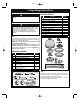
Page 3 1. Unpacking Instructions ! PACKAGE CONTENTS WARNING Part A B C D E F G H I J K L Do not install or use fan if any part is damaged or missing. ! WARNING This product is designed to use only those parts supplied with this product and/or any accessories designated specifically for use with this product. S u b s t i t u t i o n o f p a r t s o r accessories not designated for use with this product could result in personal injury or property damage.
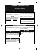
Page 4 1. Unpacking Instructions (Continued) THIS FAN IS SUITABLE FOR WET LOCATIONS SUCH AS PORCHES, PATIOS, AND DECKS. This Manual Is Designed to Make it as Easy as Possible for You to Assemble, Install, Operate and Maintain Your Ceiling Fan Your Ceiling Fan comes supplied with a RCFP Receiver and Fan Remote Control. This system allows you to regulate your ceiling fan speed and light control.
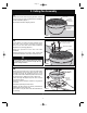
Page 5 3. Ceiling Fan Assembly 3.1 MOTOR HUB Remove the three rubber shipping spacers from the motor hub of the fan motor assembly before installation of blade assemblies (Figure 1). RUBBER SHIPPING SPACERS (3) Discard the three rubber shipping spacers. FAN MOTOR ASSEMBLY Figure 1 3.
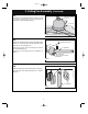
Page 6 3. Ceiling Fan Assembly (Continued) 3.4 PARTIALLY ASSEMBLED CEILING FAN Carefully turn the partially assembled ceiling fan right side up and position the fan on the styrofoam in preparation for final assembly (Figure 4). STYROFOAM Figure 4 3.5 GREEN GROUND WIRE Remove the hanger ball by loosening the Phillips head setscrew in the hanger ball until the ball falls freely down the 4.5” downrod (Figure 5). PIN Remove the pin from the 4.5” downrod, then remove the hanger ball (Figure 5). 4.
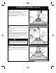
Page 7 3. Ceiling Fan Assembly (Continued) 3.7 Loosen the two setscrews in the motor coupler for installation of the downrod (Figure 7). Seat the downrod in the motor coupler (Figure 7). 4.5" DOWNROD Rotate and align the downrod holes with all the holes in the motor coupler (Figure 7). LOOSEN PHILLIPS HEAD SETSCREWS (2) MOTOR COUPLING Figure 7 3.8 Align the clevis pin holes in the downrod with the holes in the motor coupler.
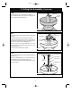
Page 8 3. Ceiling Fan Assembly (Continued) 3.10 DOWNROD Place the ceiling cover over the downrod (Figure 10). CEILING COVER Be sure that the ceiling cover and the coupling cover are both oriented correctly (Figure 10). Figure 10 3.11 PIN Route the three 80” motor leads through the hanger ball (Figure 11). 4.
Page 9 4. How to Hang Your Ceiling Fan ! CEILING WARNING The fan must be hung with at least 7' of clearance from floor to blades (Figure 13). AT LEAST 7' Figure 13 ! WARNING The outlet box and joist must be securely mounted and capable of supporting at least 50 lbs. Use only a U.L. outlet box listed as “Acceptable for Fan Support of 22.7 kg. (50 lbs.) or less”.
Page 10 4. How to Hang Your Ceiling Fan 4.2 NOTE: CEILING COVER, SUPPLY WIRES AND FAN WIRES OMITTED FOR CLARITY. Carefully lift the partially assembled ceiling fan and seat the hanger ball/downrod assembly on the hanger bracket that was just attached to the outlet box (Figure 15). OUTLET BOX Be sure the groove in the ball is engaged with the antirotation tab on the hanger bracket (Figure 15).
Page 11 5. Light Kit Assembly NOTE: If installing Ceiling Fan without the Light Kit Assembly, Skip to Section 6. Optional Installation of No-Light Plate Assembly. 5.1 Engage the white wire connector from the Fan Motor Assembly to the Light Kit Assembly white wire connector until you hear a snap (Figure 16). FAN MOTOR ASSEMBLY WHITE WIRE CONNECTOR LIGHT KIT ASSEMBLY WHITE WIRE CONNECTOR LIGHT KIT ASSEMBLY DRIVER AND ARRAY CONNECTORS Figure 16 5.
Page 12 5. Light Kit Assembly (Continued) 5.3 Remove one of the three Pan Head Screws with Lockwashers in the Light Kit Adapter and loosen the remaining two screws (Figure 18). Retain the screw and lockwasher for future use. LOOSEN THE TWO PAN HEADH SCREWS WITH LOCKWASHERS Carefully tuck all the wires into the Light Kit Adapter prior to installing the Light Kit Assembly (Figure 18). Position the Light Kit Assembly key hole slots onto the two loosened Pan Head Screws with Lockwashers.
Page 13 6. Optional Installation of No-Light Plate Assembly NOTE: To use the No-Light Plate Assembly, the Light Kit Assembly MUST NOT Be Installed, or Light Kit Assembly MUST Be Removed. H 6.1 ! WARNING Turning off wall switch is not sufficient. To avoid possible electrical shock, be sure electricity is turned off at the main fuse box before wiring.
Page 14 6. No-Light Plate Assembly (Continued) 6.4 Disengage the white wire connector from the fan motor assembly to the Light Kit Assembly white wire connector (Figure 24). Retain the Light Kit Assembly in a safe place for possible future reinstallation. FAN MOTOR ASSEMBLY WHITE WIRE CONNECTOR Tuck the fan motor assembly wires and connectors into the Light Kit Adapter adapter prior to assembling the no-light plate.
Page 15 7. How to Wire Your Ceiling Fan If you feel that you do not have enough electrical wiring knowledge or experience, have your fan installed by a licensed electrician. AC IN N GROUND WIRE WARNING TO AC IN L GREEN GROUND WIRE FROM HANGER BRACKET 7.1 ANTENNA Connect the green grounding lead from the hanger ball and the green grounding lead from the hanger bracket to the grounding conductor of supply (this may be a bare wire or wire with green colored insulation).
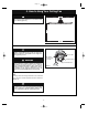
Page 16 7. How to Wire Your Ceiling Fan (Continued) 7.3 Securely connect the receiver black wire (AC in L) to the supply black wire (hot) using the wire connector (supplied in parts bag) (Figure 28). N M OT OR L TO M LIG OTO HT R N AC IN AC IN L FO R TO SUPPLY BLACK WIRE (Hot) RECEIVER BLACK WIRE (AC in L) Figure 28 7.
Page 17 7. How to Wire Your Ceiling Fan (Continued) 7.4 RECEIVER BLUE WIRE (TO LIGHT) FOR LI GHT AC IN L TOR N N TO MO AC IN TO MO TOR L Securely connect the receiver blue wire (TO LIGHT) to the fan motor blue wire using the wire connector (supplied in parts bag) (Figure 31). FAN MOTOR BLUE WIRE Figure 31 7.5 After connections have been made, position the antenna wire on top of the receiver.
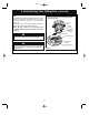
Page 18 7. How to Wire Your Ceiling Fan (Continued) 7.7 Lift the ceiling cover up to the threaded studs and turn until studs protrude through the holes in the ceiling cover (Figure 34). CEILING COVER Secure the ceiling cover in place by sliding lockwashers over the threaded studs and installing the two knurled knobs (supplied in parts bag). (Figure 34).
Page 19 8. Light Kit Assembly Replacement Repair of the Light Kit can be Accomplished By; 1) Replacing the Entire Light Kit Assembly or; 2) Replacing the Driver or Array Components Individually. 8.1 ! METHOD 1- REPLACING THE ENTIRE LIGHT KIT ASSEMBLY. ! WARNING Turning off wall switch is not sufficient. To avoid possible electrical shock, be sure electricity is turned off at the main fuse box before wiring.
Page 20 8. Light Kit Assembly Replacement (Continued) 8.4 Disengage the fan motor assembly black wire connector from the black wire connector of the new Light Kit Assembly (Figure 38). FAN MOTOR ASSEMBLY BLACK WIRE CONNECTOR Disengage the fan motor assembly white wire connector from the white wire connector of the new Light Kit Assembly (Figure 38). FAN MOTOR ASSEMBLY WHITE WIRE CONNECTOR 8.5 LIGHT KIT ASSEMBLY BLACK WIRE CONNECTOR Install new Light Kit Assembly by reversing Steps 8.4 through 8.2.
Page 21 8. Light Kit Assembly Replacement (Continued) 8.10 LIGHT KIT ASSEMBLY DRIVER TWO PIN CONNECTOR Remove the paper backing from the adhesive foam tape on the bottom of the new Light Kit Assembly Driver. Place the new Light Kit Assembly Driver into the assembly, aligning it directly where the old Driver had been (Figure 41). LIGHT KIT ASSEMBLY ARRAY CONNECTOR LIGHT KIT ASSEMBLY Press firmly on the Light Kit Assembly Driver to adhere it to the Light Kit Assembly.
Page 22 8. Light Kit Assembly Replacement 8.14 (Continued) PLASTIC PHILLIPS HEAD SCREWS (3) Unscrew the three plastic Phillips head screws securing the Light Kit Assembly Array to the Light Kit Assembly (Figure 43). LIGHT KIT ASSEMBLY ARRAY Remove the Light Kit Assembly Array from the assembly. Discard the Light Kit Assembly Array and three plastic screws in the correct recycle bin. LIGHT KIT ASSEMBLY Figure 43 8.
Page 23 8. Light Kit Assembly Replacement (Continued) 8.17 Reconnect the fan motor assembly black wire connector into the black wire connector of the Light Kit Assembly (Figure 46). The connection is complete when you hear a soft click. FAN MOTOR ASSEMBLY BLACK WIRE CONNECTOR Reconnect the fan motor assembly white wire connector into the white wire connector of the Light Kit Assembly (Figure 45). The connection is complete when you hear a soft click.
Page 24 10. Remote Control Procedures interference from other remote units such as garage door openers, car alarms or security systems. To remedy this situations, simply change the combination code in your transmitter and receiver. 10.1 Your Ceiling Fan/Light Remote Control consists of hand-held transmitter and a receiver which is mounted under the fan ceiling cover. The remote control is designed to separately control your ceiling fan speed and light intensity. 10.
Page 25 11. Setting Operating Frequency of Remote Control ! WARNING POWER INDICATOR LIGHT FAN BUTTON Fan installation must be completed, including the installation of the fan blades, before testing the remote control. 11.1 Your remote control has code switches which must be set in one of 32 possible code combinations (Figure 48). The five levers (numbered 1, 2, 3, 4, and 5) on the switches are factory-set in the ON (up) position.
Page 26 12. Maintenance IMPORTANT CARE INSTRUCTIONS for your Ceiling Fan ! WARNING Do not use water when cleaning your ceiling fan. It could damage the motor or the blades and create the possibility of an electrical shock. Periodic cleaning of your new ceiling fan is the only maintenance that is needed. When cleaning, use only a soft brush or lint free cloth to avoid scratching the finish. Abrasive cleaning agents are not required and should be avoided to prevent damage to finish. 13.
Page 27 15. Troubleshooting ! WARNING FOR YOUR OWN SAFETY TURN OFF POWER AT FUSE BOX OR CIRCUIT BREAKER BEFORE TROUBLESHOOTING YOUR FAN. TROUBLE 1. Fan will not start. PROBABLE CAUSE SUGGESTED REMEDY 1. Loose power line connections to the fan, or loose switch wire connections in the Light Kit Adapter. 1. Check line wire connections to fan and switch wire connections in the Light Kit Adapter. ! WARNING Make sure main power is turned OFF. 2. Reversing switch in neutral position. 2.
Page 28 16.
Page 29 16. Repair Parts Listing Key No. * 1 2 3 * 4 5 6 7 8 9 10 11 12 13 14 15 16 17 18 19 20 21 22 23 24 25 26 — Description Hanger Ball Assembly, Consisting of: Hanger Bracket Hanger Ball 4.
Page 30 INSTRUCTION TO THE USER (if device contains a digital device) This equipment has been tested and found to comply with the limits for a class B digital device, pursuant to part 15 of the FCC Rules. These limits are designed to provide reasonable protection against harmful interference in a residential installation.
Page 31 Air Comfort Ceiling Fan Limited Warranty 31
Page 32 SERIAL NUMBER: DATE CODE: The serial number of this fan can be found on the nameplate on top of the fan housing. The date code can be found on the carton and on top of the fan housing, stamped in ink on a white label. You should record this data above and keep it in a safe place for future use.