
Installation & Assembly

1. Unpacking Instructions
WARNING
!
WARNING
!
3
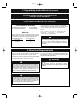
1.1
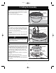
Open carton containing fan. Remove top half of
styrofoam unit. Remove parts and check to see that you
have received the following parts:
NOTE: If you are uncertain of part description, refer
to exploded view illustration.
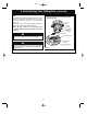
1.2
Remove the fan assembly from the protective
plastic bag. Place the fan assembly into the upper foam
pad with the bottom of the motor facing up.
The upper foam pad serves as a holder for the fan
during the first stages of assembly.
D
E
B
C
H
I
J
L
A
G
E
K
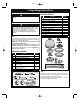
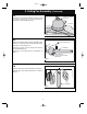
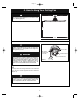
PACKAGE CONTENTS
8
7
9
1
2
3
5
4
6
Part Description Quantity
A Fan Motor Assembly 1
B Hanger Bracket 1
C Hanger Ball/4.5” Downrod 1
D Ceiling Canopy 1
E Motor Coupling Cover 1
F Fan Blade Assemblies 3
G Light Kit Adapter 1
H LED Light Kit Assembly 1
I Acrylic Shade 1
J No-Light Plate 1
K Remote Control, SR400 1
L Receiver 1
HARDWARE CONTENTS
Part Description Quantity
1 Threaded Studs, #8-32 x 1-1/4” 2
2 Knurled Knobs, #8-32 2
3 Lockwashers, External Tooth, #8 2
4 Wire Connectors 3
5 Clevis Pin 1
6 Hairpin Clip 1
7 Round Head Screws w/Lockwashers,
1/4-20 x 9/16” 16
8 Pan Head Screws w/Lockwashers,
6-32 x 5/16” (Spares) 2
9 Blade Balance Kit 1
Page 3
NOTE: Place the parts from the loose parts bags in
a small container to keep them from being lost.
If any parts are missing, call for replacement
parts before proceeding.
This product is designed to use only those
parts supplied with this product and/or any
accessories designated specifically for use with
this product. Substitution of parts or
accessories not designated for use with this
product could result in personal injury or property
damage.
Do not install or use fan if any part is damaged or
missing.