
Installation & Assembly

5
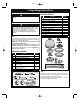
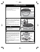
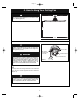
3. Ceiling Fan Assembly
FAN MOTOR
ASSEMBLY
MOTOR HUB
RUBBER
SHIPPING
SPACERS (3)
Figure 1
To reduce the risk of personal injury, do not bend the
blade assemblies when installing, balancing the blades
or cleaning the fan. Do not insert foreign objects in
between rotating fan blades.
WARNING
!
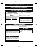
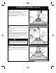
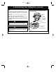
6-32 x 5/16" PAN
HEAD SCREW
W/LOCKWASHER
ROTATE CLOCKWISE
LIGHT KIT
ADAPTER
MOTOR HUB
Figure 3
3.3
Remove one of the three 6-32 x 5/16” pan head screws
with lockwashers in the motor hub of the fan motor
assembly and loosen the remaining two 6-32 x 5/16”
pan head screws with lockwashers positioned in the key
hole slots (Figure 3). Retain the screw for future use.
Position the Light Kit Adapter key hole slots onto the
two loosened screws.
Rotate the Light Kit Adapter clockwise to engage the
two screws.
Reinstall the previously removed screw.
Retighten the three screws to securely assemble the
Light Kit Adapter to the motor hub.
Spare 6-32 x 5/16” pan head screw with lockwasher in
the parts bag.
3.1
Remove the three rubber shipping spacers from the
motor hub of the fan motor assembly before installation
of blade assemblies (Figure 1).
Discard the three rubber shipping spacers.
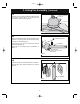
FAN MOTOR
ASSEMBLY
FAN BLADE ASSEMBLY
1/4-20 x 9/16" ROUND HEAD
SCREW WITH LOCKWASHER
(3 per blade assembly)
MOTOR HUB
Figure 2
3.2
Loosely attach one ceiling fan blade assembly to the
motor hub of the fan motor assembly using three
1/4-20 x 9/16” round head screws with lockwashers
(supplied in the parts bag) (Figure 2).
Repeat this procedure for the other two blade
assemblies.
Securely tighten the nine 1/4-20 x 9/16” round head
screws with lockwashers to the motor hub at this time.
Page 5