
Cut Sheet

®
SPECIFICATION SUBMITTAL Page
Job Name:
Job Number:
Model Numbers:
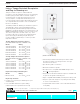
Lutron® Tamper Resistant Receptacles and Plugs
369-269 b 3 08.18.10
Wiring Diagrams Half Dimming Tamper Resistant (HDTR)
** NOTE: To control each outlet of the receptacle independently,
cut off the connecting link between the brass screws with a
wire cutter.
Ground (Green or Bare)
Live
(Black)
Neutral (White)
125 V~
60 Hz
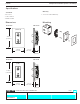
Dims lower outlet
** See Note
Below
(NTR-15-DDTR shown)
Before
After
Dimmed Live
Dimmed Live
Dims upper outlet
Each outlet will dim independently.
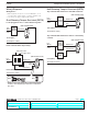
Wiring Notes:
1. Wire terminals accept 10, 12 or 14 AWG (6.0, 2.5 or
1.5 mm
2
) wire. Solid copper or copper clad wire only.
2. See device for proper strip length of wires.
Ground (Green or Bare)
Live
(Black)
Neutral (White)
Lutron
Dimming
Product
Dimmed Live
(NTR-15-DDTR shown)
Loads plugged into these outlets will dim together.
125 V~
60 Hz
Dual Dimming Tamper Resistant (DDTR)
Ground (Green or Bare)
Live
(Black)
Neutral (White)
Lutron
Dimming
Product
Dimmed Live
Live
(NTR-15-HDTR shown)
Top outlet will dim and bottom outlet will remain live.
125 V~
60 Hz
Ground (Green or Bare)
Live
(Black)
Neutral (White)
Lutron
Dimming
Product
Switch
Dimmed Live
Switched Live
(NTR-15-HDTR shown)
Top outlet will dim and bottom outlet is controlled by
a switch.
125 V~
60 Hz
3