
Specifications


5
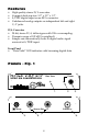
Panel Description
Front Panel
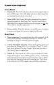
1. Data Valid: This LED indicates valid incoming digital data at
the S/PDIF Input. This LED lights whenever the Flying Calf
has acquired and locked to that data.
2.
Power LED: The Power LED lights whenever the power is
properly applied to the Flying Calf. For the Power LED to
light the power adapter must be properly plugged in and
the
Power button must be depressed.
3.
Power switch: When this button is in (and the power adapter
is properly plugged in), power is applied to the unit.
Rear Panel
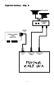
4. Power connector: For connection to the Calf’s external “wall-
wart” power supply. The Flying Calf uses a 9 Volt DC, 300
milliamp (or larger), center-pin positive supply.
5.
Analog Out (Right and Left): These are the analog audio out-
puts from the Flying Calf’s D/A converter. These 1/4" jacks
provide unbalanced line-level signals. Each jack provides a
"tip/sleeve" type of connection.
6.
S/PDIF In: This female RCA jack accepts a standard S/PDIF
digital audio input. The S/PDIF signal is "stereo," containing
both left channel and right channel audio data. The S/PDIF
data rate also determines the audio sample rate. The Flying
Calf will lock to S/PDIF sample rates of 50 kHz and below.