INBOUWKOMFOREN Gebruiksaanwijzing en installatievoorschriften NL KOCHMULDEN Gebruiksaanwijzing en installatievoorschriften ES PLACAS DE COCCIÓN EMPOTRABLES Instrucciones de uso Consejos para la instalación BUILT-IN COOKING HOBS Instruction for the use Installation advice
Nederlands Gebruiksaanwijzing en installatievoorschriften Bladzijde 3 Deutsch Gebruiksaanwijzing en installatievoorschriften Seite 22 Español Instrucciones de uso - Consejos para la instalación Página 41 English Instruction for the use - Installation advice Page 60
Nederlands Gebruiksaanwijzing en installatievoorschriften Geachte Klant, Bedankt dat u uw voorkeur heeft geschonken aan een van onze producten. De adviezen en waarschuwingen vermeld in deze gebruiksaanwijzing zijn voor uw veiligheid en die van uw naasten. Wij adviseren u deze gebruiksaanwijzing zorgvuldig door te lezen zodat u het apparaat optimaal kunt benutten.
BELANGRIJKE AANWIJZINGEN EN WAARSCHUWINGEN ✓ Verwijder de verpakking en verzeker u ervan dat het apparaat niet beschadigd is. Gebruik het apparaat niet in geval van twijfel, maar raadpleeg dan eerst uw leverancier of een bevoegd vakman. ✓ Het verpakkingsmateriaal (plastic zakken, piepschuim, spijkers, enz.) kan gevaarlijk zijn voor kinderen. Bewaar het daarom buiten het bereik van kinderen. ✓ De verpakking bestaat uit recyclebaar materiaal en is gemerkt met het kringloopsymbool .
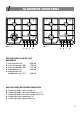
1 ALGEMENE GEGEVENS 2 2 3 3 4 4 1 5 afb. 1.1 afb. 1.2 9 6 7 8 5 6 7 8 BESCHRIJVING VAN DE GASBRANDERS 1. Snelle brander (R1) 2. Halfsnelle brander (SR) 3. Halfsnelle brander (SR) 4. Snelkookplaat (A) 5. Superbrander met driedubbele krans (TC) - 3,00 kW - 1,75 kW - 1,75 kW - 1,00 kW - 3,30 kW BESCHRIJVING BEDIENINGSKNOPPEN 5. 6. 7. 8. 9.
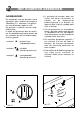
2 HET KOMFOOR GEBRUIKEN GASBRANDERS De gastoevoer naar de branders wordt geregeld door bedieningsknoppen (afbeelding 2.1) waarmee u de gaskranen van de branders opent en sluit. De gaskraan is voorzien van een veiligheidssluiting.
Ontsteking van branders MET ELEKTRISCHE ONSTEKING Deze modellen zijn te herkennen aan het symbool bij het symbool (hoogste stand, grootste gasdebiet) (afb. 2.1). Om een brander te ontsteken moet u de bijbehorende bedieningsknop indrukken en naar de hoogste stand (grote vlam) draaien; houd de bedieningsknop ingedrukt totdat de brander aan is. Regel de gaskraan op de gewenste stand.
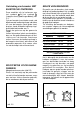
4 SCHOONMAAK EN ONDERHOUD ALGEMENE RAAD ✓ Sluit het komfoor af van het elektriciteitsnet en wacht totdat het is afgekoeld voordat u begint met het schoonmaken. ✓ Schoonmaken met een doek gedrenkt in warm water met zeep of in warm water met een vloeibaar handafwasmiddel. ✓ Gebruik geen schurende, bijtende, chloorhoudende producten en geen metalen schoonmaakgereedschap. ✓ Verwijder op het komfoor gemorste zure of basische stoffen (azijn, zout, citroenzuur, enz.) voordat zij drogen.
BRANDERS EN ROOSTERS C F S ✓ Deze kunnen van het komfoor afgenomen worden en in een sopje gewassen worden ✓ Na het schoonmaken moet u de branders goed afdrogen en zorgvuldig op hun plaats terugzetten. ✓ Het is zeer belangrijk dat u controleert of u de vlamverdeler goed teruggezet heeft, omdat een verkeerd geplaatste vlamverdeler zware storing kan veroorzaken. ✓ Bij toestellen met elektrische ontsteking moet er worden gecontroleerd of de elektrode schoon is, zodat deze goed kan vonken.
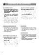
BRANDER MET DRIEDUBBELE KRANS De brander moet geplaatst worden zoals in afb. 3.2 is aangegeven. De ribben van de brander moeten in de uitsparingen steken zoals is aangeduid met de pijlen. Zet de kap A en de ring B op hun plaats (afb. 3.3 - 3.4). Als de brander goed geplaatst is kan hij niet draaien (afb. 3.3). afb. 3.4 10 afb. 3.
Aanwijzingen voor de installatie 4 INSTALLATIE IMPORTANT ✓ De installatie mag uitsluitend worden uitgevoerd door een gekwalificeerd elektricien, in overeenstemming met de lokaal geldende voorschriften en de aanwijzingen van de fabrikant. ✓ Het komfoor moet volgens de geldende voorschriften worden geïnstalleerd. ✓Schakel het komfoor altijd uit, voordat u onderhoud of reparatie uitvoert. ✓ Deze kooktoestellen zijn ontworpen voor de inbouw in een warmtebestendig keukenmeubel met een diepte van 600 mm.
Om het komfoor in het keukenmeubel in te bouwen, moet er een gat gemaakt worden met de afmetingen die zijn aangegeven in afbeelding 4.1. Bovendien moet er aan de volgende voorwaarden worden voldaan: ✓ Tussen de onderkant van het komfoor en het eronder geplaatste meubel of een ander apparaat, moet een minimale afstand van 30 mm aangehouden worden 650 mm ✓ Wanden aan de zijkant die hoger zijn dan het komfoor moeten zich minstens op een afstand van 100 mm bevinden (afb. 4.1).
KIES DE JUISTE OMGEVING Afzuigkap voor de afvoer van verbrandingsproducten H min 650 mm Het vertrek (de keuken) waar een gastoestel wordt geïnstalleerd moet voldoende geventileerd zijn voor een goede verbranding. De verse lucht moet rechtstreeks toestromen door een of meer ventilatieopeningen in de buitenmuur met een gezamenlijke doorsnede van minstens 200 cm2. De beste plaats voor de ventilatieopeningen is dicht bij de vloer, aan de overkant van de muur met de afvoeropening van de verbrandingsproducten.
; @ À @ À ; ; @ À À ; @ À ; @ MONTAGE VAN DE BEVESTIGINGSBEUGELS (afb. 4.6) ;;;;;;;; ;; Deurtje Ruimte voor aansluitingen – Leder komfoor is voorzien van een aantal beugels en schroeven voor het vastzetten in een werkblad met een dikte van 20 tot 40 mm. 30 mm Depressieruimte ;;;;;; Het keukenmeubel moet volgens specifieke eisen gemaakt zijn om te voorkomen dat de gasbranders (in de laagste stand) uitgaan bij verandering van druk door het openen of sluiten van de kastdeuren.
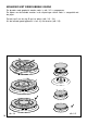
5 NL GASGEDEELTE Cat: II 2L 3B/P C F A GASAANSLUITING Het komfoor is door de fabricant ingesteld om te werken op het type gas dat op het typeplaatje en in deze handleiding is vermeld. 1/2” G kegelvorming De gasvoorziening moet voldoen aan de plaatselijk geldende voorschriften. Sluit het komfoor aan op de gasleiding of op een gasfles door middel van een roestvrijstalen gasslang die voldoet aan de plaatselijk geldende voorschriften. afb. 5.
BELANGRIJK ✓ Draai het verbindingsstuk “C” nooit zonder eerst nippel A los te maken (afb. 5.2) . Het is af te raden om het kniestuk volledig horizontaal of verticaal te zetten. ✓ De pakking “F” (afb. 5.1) is het element dat de afdichting van de aansluiting verbindingsstuk omhooglopende pijp garandeert. Het wordt aangeraden de pakking te vervangen wanneer er ook maar sprake is van een minieme vervorming of imperfectie. ✓ Controleer de dichtheid van de gasaansluiting met behulp van zeepwater.
ONDERHOUD VAN DE GASBRANDERS VERVANGING SPROEIERS VAN DE BRANDERS Ga als volgt te werk om de sproeiers te vervangen: Elk komfoor wordt geleverd met een serie sproeiers voor de verschillende gassoorten. Als er geen spuitstukken zijn meegeleverd, dan zijn deze te verkrijgen bij de Servicecentra. De nieuwe sproeiers moeten gekozen worden op grond van de “Tabel van de sproeiers”.
TABEL VAN DE INSPUITERS - Cat: II 2L 3B/P BRANDERS G30/G31 28-30/30 mbar NOMINAAL DEBIET VERMINDER DEBIET [kW] [kW] By-pass [1/100 mm] Ø spuitstuk [1/100 mm] Hulpbrander (A) 1,00 0,30 27 50 Halfsnelle (SR) 1,75 0,45 34 65 Snelle brander (R) 3,00 0,75 44 85 Driedubbele kroon (TC) 3,30 1,50 65 91 G 25 25 mbar By-pass [1/100 mm] Ø spuitstuk [1/100 mm] 72 Afstellingen NL Benodigde luchttoevoer voor de verbranding van gas (2 m3/h x kW) BRANDERS Hulpbrander (A) Halfsnelle (SR) Sn
AFSTELLING VAN HET MINIMUM VAN DE GASBRANDERS Bij de overgang van de ene gassoort naar de andere moet ook het minimumdebiet van de kraan gecorrigeerd worden, en moet de brander ook aan blijven bij een plotselinge overgang van de maximum- naar de minimumstand. DE GASKRANEN SMEREN Als een gaskraan stroef draait moet deze worden gedemonteerd, schoongemaakt met benzine en ingesmeerd met speciaal warmtebestendig vet. Deze ingreep moet door een bevoegd vakman worden gedaan.
6 ELEKTRISCHE AANSLUITING BELANGRIJK: De aansluiting op het elektriciteitsnet moet uitgevoerd worden door een bevoegd vakman en voldoen aan de geldende voorschriften. Een foute installatie kan schade aan personen, dieren en zaken ten gevolge hebben waarvoor de fabrikant zich niet aansprakelijk stelt.
DE VOEDINGSKABEL VERVANGEN DOORSNEDE VAN DE VOEDINGSKABEL - De voedingskabel mag alleen worden vervangen door een van hetzelfde type. - De draden van de voedingskabel moeten worden aangesloten op de contacten zoals aangegeven in afb. 6.1. Type “H05V2V2-F” bestand tegen een temperatuur van 90°C 230 VAC 50 Hz 3 x 0,75 mm2 230 V L1 PE N(L2) afb. 6.1 De fabrikant kan niet aansprakelijk gesteld worden voor onwaarheden in deze folder veroorzaakt door druk- of vertaalfouten.
Deutsch Gebruiksaanwijzing en installatievoorschriften Sehr geehrte Kunden, Wir danken Ihnen für das Vertrauen, das Sie uns mit dem Kauf eines unserer Haushaltsgeräte entgegengebracht haben. Die im folgenden aufgerührten Hinweise und Ratschläge dienen Ihrer Sicherheit und der anderer Personen und ermöglichen Ihnen, alle Gebrauchsweisen des Gerätes kennenzulernen.
WICHTIGE HINWEISE ✓ Kontrollieren Sie nach dem Auspacken, ob das Gerät unbeschädigt ist. Sollten Sie Zweifel haben, schalten Sie das Gerät nicht ein sondern wenden Sie sich an den Lieferanten oder an einen Elektrofachmann. ✓ Die Verpackungsteile (Plastikbeutel, Styropor, Nägel, Metallbänder etc.) müssen für Kinder unzugänglich gemacht werden, weil sie eine potentielle Gefahrenquelle darstellen.
1 ARBEITSFLÄCHE 2 3 2 3 4 4 1 5 Abb. 1.1 Abb. 1.2 9 6 7 8 GENERELLE AUSRÛSTUNG 1. Blitzbrenner (R1) 2. Schnellbrenner (SR) 3. Schnellbrenner (SR) 4. Hilfsbrenner (A) 5. Dreikranzbrenner (TR) - 3,00 kW - 1,75 kW - 1,75 kW - 1,00 kW - 3,30 kW BEDIENUNGSLEISTE 5. 6. 7. 8. 9.
2 GAS-KOCHFELD GEBRAUCH DER BRENNER (Abb. 2.1) Der Gaszufluss zum Brenner wird durch einen Bedienungsknopf (Abb. 2.1) über den Gashahn mit Sicherheits verschluss reguliert.
Zündung der Brenner MIT ELEKTRISCHER ZÜNDUNG Diese Modelle sind mit dem Symbo l neben dem Symbol Position Feuer gekennzeichnet (Abb. 2.1). Zum Einschalten des Brenners den entsprechenden Knauf eindrücken und auf maximalen Gasfluss drehen (große Flamme). Den Knauf solange gedrückt halten, bis die Zündung erfolgt ist. Gashahn auf die gewünschte Position stellen. Falls aufgrund der örtlichen Gasanlage Schwierigkeiten beim Einschalten mit dem Knauf in Position max.
4 RATSCHLÄGE FÜR DEN GEBRAUCH REINIGUNG DER KOCHFLÄCHE UND DER SCHALTERBLENDE ✓ Vor dem Reinigen der Kochmulde den Stecker aus der Steckdose ziehen und abwarten bis die Kochmulde kalt ist. ✓ Mit einem feuchten Tuch und Seife oder flüssigem Reinigungsmittel reinigen. ✓ Keine Scheuermittel, beizende, chlorhaltige Mittel oder Stahlwolle verwenden. ✓ Säurehaltige oder alkalische Flüssigkeiten sollten sofort von der Kochmulde entfernt werden (Essig, Salz, Zitronensaft usw.).
REINIGUNG DER BRENNER UND ROSTE KORREKTE ANORDNUNG DER BRENNER ✓ Diese Teile müssen abgenommen und mit geeigneten Produkten gewaschen werden. ✓ Die Brenner und die Flammenhalter müssen abgenommen und mit geeigneten Produkten gewaschen werden. ✓ Es ist sehr wichtig die genaue Position des Flammenhalters des Brenners zu prüfen, da eine ungeeignete Position schwere Störungen zur Folge haben kann.
DREIKRANZBRENNER Dieser Brenner muss gemäß Abb. 3.2 korrekt angeordnet werden. Darauf achten, dass die Rippen in den entsprechenden Sitzen einrasten (siehe Pfeil). Kappe A und Ring B richtig in den entsprechenden Sitzen anordnen (Abb. 3.3 – 3.4). Wenn der Brenner korrekt positioniert ist, darf er nicht drehen (Abb. 3.3). Abb. 3.4 Abb. 3.
Installationsanleitung 4 INSTALLATION WICHTIG ✓ Installation, Einstellung und Umrüstung des Geräts auf eine andere Gasart müssen durch einen QUALIFIZIERTEN INSTALLATEUR ausgeführt werden. ✓ Das Gerät muß ordnungsgemäß und in Übereinstimmung mit den geltenden Vorschriften installiert werden. ✓ Der Installateur hat sich an den geltenden nationalen Normen betreffend Belüftung und Entsorgung der Verbrennungsgase zu halten.
Zum Einbau der Kochmulde ist folgendes zu beachten: ✓ zwischen dem Boden der Kochmulde und der oberen Fläche eines anderen Geräts oder eines Regals, muß ein freier Raum von 30 mm übrig bleiben. ✓ Flächen, die sich neben oder oberhalb der Kochmulde befinden, müssen einen Abstand von mindestens 100 mm aufweisen (Abb. 4.1). 650 mm ✓ die Kochmulde muß von der hinteren Wand mindesten 35 mm abstehen.
INSTALLATIONSORT Der Raum, in dem das Gasgerät installiert wird, muß über eine für die Gasverbrennung notwendige Luftzufuhr verfügen (2 m3/h x kW). Die Luftzufuhr muß direkt durch eine oder mehrere Öffnungen der Außenwände erfolgen, mit einem freien Gesamtquerschnitt von mindestens 200 cm2.
;;;;;;;; ;; 30 mm Das Möbelstück muß mit geeigneten Vorrichtungen gebaut werden, um zu vermeiden, daß der durch das eventuell auch heftige Öffnen und Schließen der Türen erzeugte Druck und Unterdruck zu einem Erlöschen der Brenner führt, und zwar sowohl bei einer Minimal- als auch Maximaleinstellung. Es wird empfohlen, einen Unterdruckabstand von 30 mm zwischen dem Boden der Kochfläche und dem oberen Teil des darunter befindlichen Schranks zu lassen. Abb. 4.5 ;;;;; (Abb. 4.
5 NL GAS ABTEIL Kat: II 2L 3B/P C F A ANSCHLUSS AN DIE GASLEITUNG Die Kochmulde ist fur den am Typenschild des Geräts und in diesem Handbuch angegebenen Gastyp vorbereitet und geeicht. Die Gas-Speiseleitung muß den einschlägigen örtlichen Vorschriften entsprechen. Um die Kochmulde mit der Speiseleitung oder der Gasfläsche zu verbinden, den einem Schlauch aus rostfreiem Stahl mit durchlaufender und vorschriftsgemäßer Wand verwenden. Metallschläuche dürfen nicht länger als 2 m sein.
WICHTIG ✓ Verbindungsstück C nicht forcieren bevor der Mutter “A” gelockert worden ist (Abb: 5.2). Wir empfehlen, ihn nicht waagerecht oder senkrecht zu montieren. ✓ Die Dichtung F ist ein Teil,die die Abdichtung des Gasanschlusses 6 gewährleistet. Wir empfehlen Sie, auszuwechseln sobald sie nicht dies sobald sie nicht mehr einwandfrei ist, auszuwechseln. ✓ Nach dem Anschluß mit Wasserlauge die Abdichtung der Verbindungen kontrollieren; niemals eine Flamme dazu verwerden. Abb. 5.
WARTUNG DES KÜCHENHERDS AUSTAUSCH DER DÜSEN Die Ersatzdüsen sind bei den Kundendienststellen erhältlich. Für die Wahl der zu ersetzenden Düsen muß die Düsentabelle eingesehen werden. Der in Hundertstel-Millimeter ausgedrückte Düsendurchmesser ist auf jeder Düse angegeben. Um die Düsen auszuwechseln, folgendermaßen vorgehen: ✓ Die Roste und die Brenner von der Kochmulde abnehmen. ✓ Mit einem Maulschlüssel die Düsen "J" (Abb. 5.3 - 5.
TABELLE DER GASDÜSEN - Kat: II 2L 3B/P BRENNER Nennleistung [kW] Reduzierte Leistung [kW] Hilfsbrenner (A) 1,00 Normalbrenner (SR) Starkbrenner (R) Dreikranzbrenner (TR) G30/G31 28-30/30 mbar By-pass [1/100 mm] Ø Duse [1/100 mm] 0,30 27 50 1,75 0,45 34 65 3,00 0,75 44 85 3,30 1,50 65 91 G 25 25 mbar By-pass [1/100 mm] Einstellbar NL Ø Duse [1/100 mm] 72 94 121 130 ERFORDERLICHE LUFTZUFUHR FÜR DIE GASVERBRENNUNG (2 m3/h x kW) BRENNER Hilfsbrenner (A) Erforderliche Luftzufuhr [m3/h
EINSTELLUNG DES MINDESTDURCHFLUSSES DER GASBRENNER Wenn auf eine andere Gassorte umgerüstet wird, ist auch der Mindestdurchfluss am Hahn neu einzustellen. In dieser Position muss die Flamme etwa 4 mm lang sein und muss auch dann weiterbrennen, wenn von maximalem auf minimalen Gasfluss umgestellt wird. SCHMIERUNG DER GASHÄHNE Wenn der Gashahn beim Drehen klemmt, muss er von Fachpersonal ausgewechselt werden. Die Flamme wird folgendermaßen eingestellt: – Brenner einschalten.
6 ELEKTRISCHER TEIL Wichtig: Der Einbau und Anschluß muß genau nach den Anweisungen des Herstellers erfolgen. Ein fehlerhafter Anschluß kann Schäden an Personen, Tieren und Sachen verursachen, für die der Hersteller keinerlei Haftung übernimmt. ALLGEMEINES ✓ Der Anschluß des Gerätes muß von einem qualifizierten Techniker nach den geltenden Sicherheitsvorschriften ausgeführt werden.
Auswechseln des Speisekabels Schnitt der Speisekabel Kabel Typ “H05V2V2-F” - Das Speisekabel darf nur mit einem gleichartigen Kabel ausgewechselt werden, wie das das am Gerät montiert ist. hitzebeständig bis zu 90°C 230 VAC 50 Hz 3 x 0,75 mm2 - Das neue Speisekabel, dessen Typ und Schnitt geeignet sein müssen, laut dem unten aufgeführten Schema anschließen. 230 V L1 PE N(L2) Abb. 6.1 Die Beschreibung in dieser Gebrauchs-Anweisung ist rein informativ.
Español Instrucciones de uso - Consejos para la instalación Apreciado Cliente: Le agradecemos por la confianza que nos ha brindado comprando nuestro producto. Las advertencias y los consejos descritos a continuación tienen la función de proteger su seguridad y la de los demás. Además le permitirán disfrutar de las ventajas que el aparato le ofrece. Guarde con cuidado este folleto, le será útil en futuro, en el momento en que Usted, o quien por Usted, tuviera dudas sobre su funcionamiento.
ADVERTENCIAS Y CONSEJOS IMPORTANTES ✓ Después de haber quitado el embalaje, asegúrese de la integridad del aparato. En caso de dudas no lo utilice y contacte al vendedor o a personal profesionalmente cualificado. ✓ El material de embalaje (bolsas de plástico, poliestireno celular, clavos, cintas, etc.) no se debe dejar al alcance de los niños, ya que pueden ser peligrosos. ✓ El embalaje está formado por material reciclable y está marcado por el símbolo .
1 CARACTERÍSTICAS 2 3 2 3 4 4 1 5 Fig. 1.1 9 6 7 8 Fig. 1.2 5 6 7 8 DESCRIPCÍÓN FUEGOS 1. Quemador rápido (R1) - 3,00 kW 2. Quemador semirápido (SR) - 1,75 kW 3. Quemador semirápido (SR) - 1,75 kW - 1,00 kW 4. Quemador auxiliar (A) 5. Quemador triple corona (TR) - 3,30 kW DESCRIPCION DE LOS MANDOS 5. 6. 7. 8. 9.
2 PIANO DE COCCION GAS QUEMADORES DE GAS La entrada de gas en los quemadores esta regulada por las empuñaduras de la fig. 2.1 que controlan los grifos de cierre de seguridad. Haciendo coincidir el índice de la empuñadura con los símbolos impresos en el cuadro de distribución del aparato se obtiene: – disco lleno ● = grifo cerrado – símbolo – símbolo = abertura max. o capacidad max. = abertura min. o capacidad min.
Quemadores de gas CON ENCENDIDO ELÉCTRICO Los modelos se identifican por el símbolo cerca del símbolo - (apertura máx o capacidad máx) (fig. 2.1). Para encender uno de los quemadores, presione y gire el botón correspondiente, hasta la posición de capacidad máxima (llama grande) y manténgalo presionado hasta que se encienda el quemador. Ajuste el grifo del gas en la posición deseada.
4 LIMPIEZA Y MANTENIMIENTO CONSEJOS GENERALES TAPA DE VIDRIO (optional) ✓ No realice alguna operación de limpieza sin haber antes desconectado el aparato de la red de alimentación y esperar que se haya enfriado. ✓ Limpie la placa con un paño humedecido en agua caliente y jabón o agua y detergente líquido. ✓ No utilice productos abrasivos, corrosivos, lejías o estropajos de virutas metálicas. ✓ Evite dejar sobre la superficie de cocción sustancias alcalinas o ácidas (zumo de limón, vinagre, etc.).
QUEMADORES Y PARRILLAS Es posible sacar estas piezas para lavarlas con productos adecuados. Después de la limpieza, seque correctamente los quemadores y mecheros y los vuelva a colocar correctamente en su alojamiento. C Es muy importante comprobar la perfecta colocación del mechero del quemador porque si se mueve de su alojamiento puede causar graves anomalías. F Nota: Para prevenir daños al encendido eléctrico, no lo utilice cuando los quemadores no estén en su alojamiento.
QUEMADOR TRIPLE CORONA Este quemador debe estar colocado correctamente como se indica en la fig. 3.2, prestando atención a que las nervaduras entren en su alojamiento como indicado por la flecha. Coloque correctamente en su alojamiento la tapa A y el anillo B (fig. 3.3 - 3.4). El quemador correctamente colocado no debe girar (fig. 3.3) Fig. 3.4 48 Fig. 3.
Consejos para la instalación 4 INSTALACIÓN IMPORTANTE ✓ La instalación, regulación y transformación de la plataforma de cocción a otros gases tiene que ser efectuada por un INSTALADOR CALIFICADO. ✓ El equipo tiene que instalarse correctamente y en conformidad con la normativa vigente. ✓ El encargado de la instalación debe respetar las normas locales vigentes en materia de ventilación y descarga de los gases de combustión. ✓ Cualquier intervención en el equipo tiene que efectuarse sin tensión eléctrica.
Para empotrar la placa en el mueble es necesario efectuar una abertura de las dimensiones indicadas en la fig. 4.1, teniendo presente que: ✓ En el interior del mueble, entre el fondo de la placa y la parte superior de una repisa debe haber una distancia mínima de 30 mm. 650 mm ✓ Cualquier pared al lado que sobresalga la placa tiene que estar a una distancia mínima de 100 mm (fig. 4.1). ✓ La pared detrás de la placa de cocción debe estar a una distancia mínima de 35 mm (fig. 4.1).
LOCAL DE INSTALACIÓN Campana de evacuación de los gases de combustión H min 650 mm El local donde se desea instalar la placa a gas debe tener una buena ventilación ya que es necesario para la combustión del gas (de acuerdo con las normas locales vigentes). La entrada de aire se debe producir directamente desde una o más aberturas efectuadas en las paredes externas con una sección libre total de al menos 200 cm2.
; @ À @ À ; ; @ À À ; @ À ; @ MONTAJE DE LAS ALETAS DE FIJACIÓN (fig. 4.6) ;;;;;;;; ;; 30 mm ;;;;;; El mueble debe ser construido con las oportunas precauciones para evitar que la presión y la depresión provocadas por la apertura y cierre, incluso violentos, apaguen los quemadores regulados al mínimo o al máximo. Se aconseja dejar un espacio de depresión de 30 mm entre el fondo de la placa y la parte superior del mueble. Fig. 4.5 ;;;;;;;; INSTALACION EN MUEBLES CON PUERTAS (fig. 4.
5 ES GAS SECTION Cat: II 2H3+ C F A CONEXIÓN A LA RED DE GAS La placa de cocción está predispuesta y calibrada con el gas indicado en la placa de características aplicada en el aparato. La instalación del gas debe estar conforme a las normas locales vigentes. 1/2” G F Fig. 5.1 Para la conexión de la placa a la red del gas o a la bombona, utilice un tubo flexible en acero inox con pared continua según la norma local. Utilice la guarnición F para la unión cilíndrica en codo.
IMPORTANTE: ✓ No gire jamás la unión C con fuerza sin haber previamente aflojado la tuerca “A” (fig. 5.2). Se aconseja no dejarlo jamás en posición horizontal o vertical. ✓ La guarnición F (fig. 5.1) es el elemento que garantiza la estanqueidad de la conexión del gas. Se aconseja sustituirla al presentar incluso una mínima deformación o imperfección. ✓ Después de efectuar la conexión, compruebe la estanqueidad de la misma con una solución iabonosa. jamás nasanda una llama 54 Fig. 5.
GAS MAINTENANCE ADAPTACIÓN A LOS DIFERENTES TIPOS DE GASES SUSTITUCIÓN DE LOS INYECTORES DE LOS QUEMADORES Si se utiliza un gas diferente del indicado en la etiqueta, es necesario adaptar la placa a esta nueva función: 1. Cambie los inyectores con otros apropiados. 2. Efectúe la regulación del mínimo de los quemadores. Cada placa tiene está provista de una serie de inyectores para los varios tipos de gas. Si no se suministran con la placa, es posible pedir los inyectores a los Centros de Asistencia.
TABLA DE INYECTORES - Cat: II 2H 3+ ES QUEMADOR PORTADA NOMINAL [kW] PORTADA REDUC.
REGULACIÓN DEL MÍNIMO EN LOS QUEMADORES DE GAS En el pasar de un tipo de gas a otro, también la capacidad mínima de los grifos tiene que ser corregida, y tiene que quedar encendida también con un cambio brusco entre la posición de máximo a la de mínimo. La corrección se efectúa , con los quemadores encendidos, en la siguiente manera: – Encender el quemador – Girar el grifo en la posición de mínimo.
6 PARTE ELÉCTRICA lMPORTANTE!: La instalación debe ser efectuada según las instrucciones del fabricante. Una instalación incorrecta puede causar daños a personas, animales o cosas, por los cuales el fabricante declina toda responsabilidad. CONEXIÓN A LA RED ELÉCTRICA ✓ La conexión a la red eléctrica debe ser efectuada por personal especializado y según las normas vigentes. N.B.
Cambio del cable de alimentación - El cable de alimentación debe ser sustituido con un cable del mismo tipo del montado en el aparato. - El cable eléctrico debe estar conectado con la regleta de bornes de acuerdo con el esquema expuesto en la fig. 6.1. SECCIÓN DE LOS CABLES DE ALIMENTACIÓN “H05V2V2-F” Resistentes a la temperatura de 90°C 230 VAC 50 Hz 3 x 0,75 mm2 230 V L1 PE N(L2) Fig. 6.
English Instruction for the use - Installation advice Dear Customer, Thank you for having purchased and given your preference to our product. The safety precautions and recommendations given below are for your own safety and that of others. They will also provide a means by which to make full use of the features offered by your appliance. Please keep this booklet carefully. It may be useful in future, either to yourself or to others if doubts should arise relating to its operation.
IMPORTANT PRECAUTIONS AND RECOMMENDATIONS ✓ After having unpacked the appliance, check to ensure that it is not damaged. If you have any doubts, do not use it and consult your supplier or a professionally qualified technician. ✓ Packing elements (i.e. plastic bags, polystyrene foam, nails, packing straps, etc.) should not be left around within easy reach of children, as these may cause serious injuries. ✓ The packaging material is recyclable and is marked with the recycling symbol .
1 FEATURES 2 3 2 3 4 4 1 5 Fig. 1.1 9 6 7 8 Fig. 1.2 DESCRIPTION OF BURNERS 1. Rapid burner (R1) 2. Semirapid burner (SR) 3. Semirapid burner (SR) 4. Auxiliary burner (A) 5. Triple-ring burner (TR) - 3,00 kW - 1,75 kW - 1,75 kW - 1,00 kW - 3,30 kW CONTROL PANEL DESCRIPTION 5. 6. 7. 8. 9.
2 GAS BURNERS GAS BURNERS Gas flow to the burners is adjusted by turning the knobs illustrated in fig. 2.1 which control the safety valves. Turning the knob so that the indicator line points to the symbols printed on the panel achieves the following functions: – full circle ● = closed valve – symbol = maximum aperture or flow – symbol = minimum aperture or flow ✓ To light one of the gas burners, hold a flame (e.g.
Lighting the burners WITH ELECTRIC IGNITION To light one of the burners, press and turn the corresponding knob to the maximum flow position (large flame ) and keep the knob pressed down until the gas is lit (fig. 2.2). Turn the gas tap to the position required. Whenever special conditions of the gas supplied locally make it difficult to light the burner with the knob in the maximum flow position, repeat the operation with the knob in the minimum flow position.
3 CLEANING AND MAINTENANCE GENERAL ADVICE ✓ Before you begin cleaning you must ensure that the hob is switched off. It is advisable to clean when the appliance is cold and especially when cleaning the enamelled parts. ✓ All enamelled surfaces have to be washed with soapy water or some other non-abrasive product with a sponge and are to be dried preferably with a soft cloth. ✓ Avoid leaving alkaline or acid substances (lemon juice, vinegar etc.) on the surfaces.
BURNERS AND GRIDS ✓ These parts can be removed and cleaned with appropriate products. ✓ After cleaning, the burners and their flame spreaders must be well dried and correctly replaced. C ✓ It is very important to check that the burner flame spreader and the cap have been correctly positioned. Failure to do so can cause serious problems. F ✓ In appliances with electric ignition keep the electrode clean so that the sparks always strike.
CORRECT POSITION OF TRIPLE RING BURNER The triple ring burner must be correctly positioned (see fig. 3.2); the burner rib must be fitted in their housing as shown by the arrow. Then position the cap A and the ring B (fig. 3.3 - 3.4). The burner correctly positioned must not rotate (fig. 3.3). Fig. 3.4 Fig. 3.
Installation advice 4 INSTALLATION IMPORTANT ✓ The appliance should be installed, regulated and adapted to function with other types of gas by a QUALIFIED INSTALLATION TECHNICIAN. ✓ The appliance must be installed in compliance with regulations in force in your country and in observation of the manufacturer's instructions. ✓ Always unplug the appliance before carrying out any maintenance operations or repairs. ✓ The appliance must be housed in heat-resistant units.
In order to install the cooker top into the kitchen fixture, a hole with the dimensions shown in fig. 4.1 has to be made, bearing in mind the following: ✓ within the fixture, between the bottom side of the cooker top and the upper surface of any other appliance or internal shelf there must be a clearance of at least 30 mm; 650 mm ✓ the cooker top must be kept no less than 100 mm away from any side wall (fig. 4.1). ✓ the hob must be installed at least 35 mm from the wall.
CHOOSING SUITABLE SURROUNDINGS DISCHARGING PRODUCTS OF COMBUSTION In the room chosen to accommodate the gas appliance, there must be an adequate natural draft to allow combustion of the gas. The flow of air must come directly from one or more openings made in the outside walls with a free area of at least 200 cm2. Extractor hoods connected directly to the outside must be provided, to allow the products of combustion of the gas appliance to be discharged (fig. 4.3).
; @ À @ À ; ; @ À À ; @ À ; @ INSTALLATION IN KITCHEN CABINET WITH DOOR (fig. 4.5) FASTENING THE INSTALLATION BRACKETS (fig. 4.6) ;;;;;;;; ;;;;;;;; ;; 30 mm ;;;;;; The fixture has to be made according to specific requirements in order to prevent the gas burners from going out, even when the flame is turned down to minimum, due to pressure changes while opening or closing the cupboard doors. It is recommended that a 30 mm clearance be left between the cooker top and the fixture surface (fig.
5 GAS SECTION NL Cat: II 2L 3B/P ES Cat: II 2H3+ C GAS CONNECTION F A 1/2” G conical The cooktop is set up and calibrated to work with the gas indicated on the rating plate affixed to the appliance and on this instruction booklet. NL The gas supply system must conform to the local regulations in force. To conned the cooktop to the gas mains or cylinder use a flexible stainless steel hose with continuous wall conforming to local regulations. Use gasket F for the cylindrical elbow connection.
IMPORTANT ✓ Never attempt to turn the fitting C without having first slackened off the relative lock nut (fig. 5.2). ✓ The seal F (fig. 5.1) is the element that guarantees the seal in the piperamp connector. It is recommended that it be replaced whenever it shows even the slightest deformation or imperfection. ✓ After connecting to the mains, check that the couplings are correctly sealed, using soapy solution, but never a naked flame. Fig. 5.
GAS MAINTENANCE ADAPTING THE APPLIANCE TO FUNCTION WITH DIFFERENT TYPES OF GAS OPERATIONS TO BE PERFORMED WHEN SUBSTITUTING THE INJECTORS If a different gas from that one indicated on the label is used, you need to adapt the cooktop to this new situation. If the injectors are not supplied they can be obtained from the “Service Centre”. Select the injectors to be replaced according to the table on next page.
TABLE FOR THE CHOICE OF THE INJECTORS - Cat: II 2L 3B/P BURNERS Nominal power [kW] Reduced power [kW] Auxiliary (A) 1,00 Semirapid (SR) 1,75 Rapid (R) Triple-ring (TR) ES G30/G31 28-30/30 mbar By-pass [1/100 mm] Ø injector [1/100 mm] 0,30 27 50 0,45 34 65 3,00 0,75 44 85 3,30 1,50 65 91 G 25 25 mbar By-pass [1/100 mm] Ø injector [1/100 mm] 72 Adjustable NL 94 121 130 TABLE FOR THE CHOICE OF THE INJECTORS - Cat: II 2H 3+ BURNERS Auxiliary (A) Nominal power [kW] Reduced powe
REGULATING THE BURNER MINIMUM SETTING LUBRICATING THE GAS TAPS When switching from one type of gas to another, the minimum flow rate must also be correct: the flame should not go out even when passing suddenly from maximum to minimum flame. To regulate the flame follow the instructions below: – Light the burner – Set the cock valve to minimum If one of the gas taps becomes hard to turn, dismantle it, thoroughly clean with petrol and apply special high-temperature grease.
6 ELECTRICAL SECTION IMPORTANT: Installation has to be carried out according to the instructions provided by the manufacturer. Incorrect installation might cause harm and damage to people, animals or objects, for which the manufacturer accepts no responsibility.
REPLACING THE POWER SUPPLY CABLE FEEDER SPECIAL CABLE SECTION Type “HO5V2V2-F” Use the same type of power supply cable. This cable must be connected to the terminal block following the diagram in fig. 6.1. resistance to temperatures of 90°C 230 VAC 50 Hz 3 x 0,75 mm2 230 V L1 PE N(L2) Fig. 6.1 Descriptions and illustrations in this booklet are given as simply indicative.
1102135 ß1