DVR-9404~9408~9416 Mace Security Products Table of Contents Page 1 Introduction Chapter 1 3 Hardware Installation 1.1 Video Capture Device Installation ………………………………………………………………….. 3 1.1.1 Install GV-100 Hardware ……………………………………………………………… 3 1.1.2 Install GV-150 Hardware ……………………………………………………………… 3 1.1.3 Install GV-250 Hardware ……………………………………………………………… 4 1.1.4 Install GV-600 Hardware ……………………………………………………………… 5 1.1.5 Install GV-650 / GV-750 / GV-800 Hardware ………………………………………. 6 1.
DVR-9404~9408~9416 Mace Security Products 3.2.3 System Setup and Configuration……………………………………………… 26 General Setting ………………………………………………………………… 26 Camera Setting ………………………………………………………………… 31 I/O Device Setting ……………………………………………………………… 35 Hotline / Network Configuration ………………………………………………. 38 Camera / Audio Install …………………………………………………………. 41 Auto Reboot Setup …………………………………………………………….. 42 Password Setup ………………………………………………………………... 43 Email Setup ……………………………………………………………………..
DVR-9404~9408~9416 Mace Security Products Connection Button ……………………………………………………………... 64 Disconnect Button ……………………………………………………………… 65 Search Button …………………………………………………………………... 65 List View ………………………………………………………………………… 67 Connection Record …………………………………………………………….. 68 Address Book …………………………………………………………………... 69 Preferences Setting ……………………………………………………………. 70 5.2.3 RPB Playback Control Panel …………………………………………………. 71 5.2.4 Saving a Snapshot as AVI Movie ……………………………………………..
DVR-9404~9408~9416 Chapter 8 Mace Security Products Backup System and Repair Database Utility 8.1 Backup System ……………………………………………………………………………………. 127 8.2 Backup Audio / Video Files ………………………………………………………………………. 128 8.3 Remote Backup …………………………………………………………………………………… 131 8.4 Delete Audio Video Files ………………………………………………………………………… 132 8.5 Repair Database Utility …………………………………………………………………………… 133 Chapter 9 Watermark Proof 9.
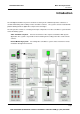
DVR-9404~9408~9416 Mace Security Products Introduction Introduction The GV Digital Surveillance System is an advanced, total system solution that provides continuous or scheduled monitoring and recording of video surveillance cameras. The system is based on standard PC platform utilizing the latest digital video compression technologies. The GV System as a whole is consisting of two major components: The video surveillance system and the remote monitoring system.
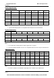
DVR-9404~9408~9416 Mace Security Products Introduction Product Specification Video Channel Video Device Recording Rate Compression (NTSC / PAL) Format Audio Channel Real Time Display Card GV-100 1, USB Camera 30 / 30 Wavelet / MPEG4 N/A N/A GV-150 2, 4 USB Grabber 40 / 32 Wavelet / MPEG4 N/A N/A GV-250 2, 4, 6, 8, 10, 12, 14, 16 Video Card 20 / 16 Wavelet / MPEG4 N/A N/A GV-600 4, 6, 8, 10, 12, 14, 16 Video Card 30 / 25 Wavelet / MPEG4 1 Yes GV-650 4, 8, 12, 16 Video
DVR-9404~9408~9416 Mace Security Products Chapter 1 Hardware Installation Chapter 1 Hardware Installation The Hardware components included in your system may vary depending on the model or optional features you purchased. This chapter will describe all available hardware components of the GV-System and its installation procedures. 1.1 Video Capture Device Installation 1.1.1 GV-100 Installation The GV-100 support only one port and is the most basic model in the GV-Series.
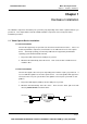
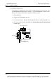
DVR-9404~9408~9416 Mace Security Products Chapter 1 Hardware Installation 1.1.3 Install GV-250 Hardware The GV-250 uses a PCI interface video capture card that supports from 2 to 16 ports. The standard GV-250 will support either 2 or 4 ports. If you are installing a 6~16 ports system then you are require to connect video extension card to the system. 1. Power-off the PC. 2. Insert PCI card (GV-250) into PCI slot. 3. Turn on the PC power. Windows will automatically detect the existing (GV-250) card. 4.
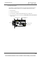
DVR-9404~9408~9416 Mace Security Products Chapter 1 Hardware Installation 1.1.4 Install GV-600 Hardware The GV-600 uses a PCI interfaced card and is one of the models that support Real Time Display card and Audio Recording card. The GV-600 will support from 4 to 16 ports. 1. Power-off the PC. 2. Insert PCI card into PCI slots. 3. Turn on PC power. Windows will automatically detect the existing cards. 4.
DVR-9404~9408~9416 Mace Security Products Chapter 1 Hardware Installation 1.1.5 Install GV-650 / GV-750 / GV-800 Hardware The GV-650, GV-750, and GV-800 are identical in card layout; the only difference is in the performance. All three models support the optional Real Time Display card and audio recording card. The standard model starts from 4 ports with optional expansion to 8, 12, and 16 ports. 1. Power-off the PC. 2. Insert PCI card into PCI slots. 3. Turn on PC power.
DVR-9404~9408~9416 Mace Security Products Chapter 1 Hardware Installation 1.2 Watchdog Installation for GV-600 / GV-650 / GV-750 / GV-800 The Watchdog is a mechanism that is used to determine whether another mechanism is alive or not. In other words, if for some reason a system is down or "hang up", watchdog will automatically reboot the PC. The watchdog will restart the computer automatically if it did not receive any response from the system for more than 5 minutes.
DVR-9404~9408~9416 Mace Security Products Chapter 1 Hardware Installation 1.4 Real Time Display Card Installation The Real Time Display card is capable of feeding 480 fps to 16 video channels with each channel running at 30 fps. Video can also be displayed to a TV monitor by using the TV-out connector. The card is designed to work conjunctionally with your GV series video capture card; therefore, a direct connection between both cards is required.
DVR-9404~9408~9416 Mace Security Products Chapter 1 Hardware Installation 1.5 Audio Extension Card Installation The Audio Extension Card adds audio recording capability to your GV-System. Currently the models that support audio recording function are GV-600, GV-650, GV-750, and GV-800, which support 1, 2, 3, and 4 recording channels respectively. To install the Audio Extension Card simply plug the output cord of the extension card into the audio input connector of your video capture card.
DVR-9404~9408~9416 Mace Security Products Chapter 1 Hardware Installation Page 10 FOR ADDITIONAL QUESTIONS CONTACT TECHNICAL SUPPORT TEAM @ 1 (866) 392-MACE
DVR-9404~9408~9416 Mace Security Products Chapter 2 Software Installation Chapter 2 Software Installation All GV-Series software applications are included in the CD-ROM provided within the system package. There are total 7 software applications inside the CD-ROM including Main System Application, Remote View, IP Multicast, GeoCenter, Register Dynamic IP, Remote Playback and PDA Viewer. The Main System Application and Register Dynamic IP Application should be install in the video surveillance system.
DVR-9404~9408~9416 Mace Security Products Chapter 2 Software Installation 2.1 Install Main System Application Before starting the installation of your Main System Application, you should check if all hardware components were installed properly. It is important that you complete the hardware installation in Chapter one first before proceeds to the software installation procedures below. 1. Insert GV-Series CD into the CD-ROM drive of your GV-System and run Setup.exe in the CD-ROM root directory. 2.
DVR-9404~9408~9416 Mace Security Products Chapter 2 Software Installation 5. Now select the video standard for the source camera used in the system and click [Next]. There are 3 options: NTSC, PAL, and SECAM. You can also change the video standard later in the configuration of the Main System Application. 6. Click [Browse] if you wish to specify another destination directory otherwise click [Next] to proceed to the next step.
DVR-9404~9408~9416 Mace Security Products Chapter 2 Software Installation 7. In the select program dialog box you may change the name for your GV-System folder in the empty text column under Program Folder. If you are not sure what to do in this area simply click [Next] and the installation will start. Follow the rest of the instruction to complete the installation. 2.2 Uninstall Main System’s Application To uninstall GV-Series System, click on the Uninstall icon from the folder.
DVR-9404~9408~9416 Mace Security Products Chapter 3 Main System Application CHAPTER 3 Main System Application The Main System Application is Windows-based GUI system software that is used for control, setup, and monitor the GV-System. This chapter contains two sections: the first section will describe the function and features of the main screen, while the second section describes the detail of main screen’s function panel. 3.
DVR-9404~9408~9416 Mace Security Products Chapter 3 Main System Application 3.1.1 Status Panel Status Panel Indicates the available HD space, system date/time, and the enabled network functions such as Modem, TCP and MultiCast, etc… Time / Date Hard Disk Space Enabled Network Function 3.1.2 PTZ Control Panel Before you can use the PTZ control panel you should have at least one PTZ camera installed within your GV-System first.
DVR-9404~9408~9416 Mace Security Products Chapter 3 Main System Application 3.1.3 I/O Control Panel Press the I/O icon to open the I/O control interface. I/O Input Panel: The I/O input panel displays the status of the input sensors from module 1 to module 9. Module Number Input Device I/O output panel: Sending the output signals to the relays or alarms of module 1 to module 9. (PT811 support output 1~8, GV-IO support output 1~16) Module Number Output Device 3.1.
DVR-9404~9408~9416 Mace Security Products Chapter 3 Main System Application 3.1.5 Display Layout Panel The display layout panel allows you to choose from 8 different display layout options. 3.1.6 Exit and Minimize Button The [Exit] button contains four functions: Login/Exchange User, Logout User, Minimize, and Exit. Login/Exchange User: Allows you to login as a different user. Logout User: Allows you to logout from the system. Minimize: Hide main screen in Windows status bar.
DVR-9404~9408~9416 Mace Security Products Chapter 3 Main System Application Snapshot: [Snapshot] allows you to capture a camera image and save them as avi., bmp., Jpeg., or tif. files. Click on the camera caption of the camera view window, and the following dialogue box will appear. You may tag camera descriptions in the image file such as time/date, camera number, location, and choose color for the description background by clicking the option boxes below.
DVR-9404~9408~9416 Mace Security Products Chapter 3 Main System Application 3.2 Function Panel The Function Panel provides access to most of the GV-System’s function and configuration. There are six buttons in the function panel with each button containing its own menu. 3.2.1: Start/Stop Monitoring 3.2.2: Schedule Setup 3.2.3: System Configure 3.2.4: View Log 3.2.5: Camera Scan 3.2.6: Network Function 3.2.
DVR-9404~9408~9416 Mace Security Products Chapter 3 Main System Application 3.2.2 Schedule Click on the [Schedule] button and the following dialog box will appear. There are two types of surveillance schedules in GV-System: the video surveillance schedule and the I/O surveillance schedule. Each can be setup in weekly basis or exclusively by date. Your GV-System is capable of running multiple surveillance schedules; therefore, you can assign each camera with a different schedule.
DVR-9404~9408~9416 Mace Security Products Chapter 3 Main System Application Step Two: Specify monitor invoke options Rec: Click on the Rec option to enable or disable recording function. Recording Mode: Use the drop-down menu to choose between Round-the-clock recording mode or Motion-detect recording mode. Round-the clock mode applies full time recording during the schedule period while Motion-detect mode records only when motions are detected.
DVR-9404~9408~9416 Mace Security Products Chapter 3 Main System Application Step Six: Add schedule to the list You have now complete the setup of this weekly schedule, click [add schedule] button to add this schedule to the list. Detail of your schedules will be listed in the Schedule List Window. You can also view each camera’s surveillance schedule in bar chart view by clicking the camera select tab below the Schedule List Window.
DVR-9404~9408~9416 Mace Security Products Chapter 3 Main System Application Setup video surveillance schedules for Holidays: You may want to setup different schedules for Holidays such as Christmas or New Year. You can setup all holiday under the same schedules or you can assign different schedules for each holiday. Click the [Holiday schedule] control tab to switch to holiday setup window.
DVR-9404~9408~9416 Mace Security Products Chapter 3 Main System Application How to setup I/O surveillance schedules: The I/O surveillance schedule works similarly as the video surveillance schedule with simpler operation. Click on the I/O schedules control tab to switch to I/O schedule setup window. Step one: Select time period Set starting and ending time of your preferred schedule event. Step Two: Select I/O Device Select the I/O device to be included in this surveillance schedule.
DVR-9404~9408~9416 Mace Security Products Chapter 3 Main System Application 3.2.3 System Setup and Configuration Press the [System Configure] button or [F9] shortcut key on your keyboard for system configuration setup. There are total 8 options included in the Configure menu. This section will explain each option in detail. System Configuration The System Configuration window includes four types of configuration setup: General Setting, Camera Setting, I/O Device Setting, and Hotline/Network Setting.
DVR-9404~9408~9416 Mace Security Products Chapter 3 Main System Application [Start Up] In Startup area you can choose which functions you wish to enable when starting up your GV-System. Click on the check box before each function to enable and uncheck it to disable. Start Monitor: If this function is enabled the system will automatically start monitoring when starting up GV-System.
DVR-9404~9408~9416 Mace Security Products Chapter 3 Main System Application [Exit Option] Two options are available: auto shutdown windows and auto restart windows. If you select auto shutdown windows the system will automatically shutdown Windows OS after you exit GV-System. If you choose auto restart windows then it will automatically restart Windows OS after you exit GV-system. [Location Name] Allow you to specify a name for your GV-system, maximum 14 characters.
DVR-9404~9408~9416 Mace Security Products Chapter 3 Main System Application [PTZ Control] The PTZ Control allows you to setup installed PTZ cameras. Select the make and models in the drop down list menu and click the PTZ setup button to activate it. If you cannot find your PTZ camera within the drop down list then most likely its not supported by the GV-System. [Monitor Option] Specify how many seconds to delay monitoring function after system startup.
DVR-9404~9408~9416 Mace Security Products Chapter 3 Main System Application [Camera Scan] Allow you to specify the Scan Delay from 1 to 10 seconds. Click on the [Arrow] icon and you can choose between single camera scan or four cameras scan. [Video Record] Click on the box of Digital Watermark Protection to activate the function of Digital Watermark in order to prevent artificial alteration or distortion of recorded events.
DVR-9404~9408~9416 Mace Security Products Chapter 3 Main System Application Camera Setting Camera setting window allows you to configure each camera’s motion detection sensitivity, recording quality, video adjustment, and etc… Each camera has its own setup window and you can use the camera control tab to switch between the cameras. [Camera Name] You can specify a name for each camera. You can name each camera according to its location or usage.
DVR-9404~9408~9416 Mace Security Products Chapter 3 Main System Application [Rec Control] The Rec Control area allows you to set each camera’s recording quality. The camera’s recording quality is based on its resolution and compression rate. Higher quality picture will require more storage spaces. Apply to all cameras Rec quality adjust Resolution button Frame rate setup Smart Recording Option Select high/low frame rate Recording Quality: Allows you to adjust the video quality in 5 levels.
DVR-9404~9408~9416 Mace Security Products Chapter 3 Main System Application Frame Rate Setup: Allows you to limit camera’s maximum recording frame rates. If the value you specify is 10 then it means this camera will not exceeds 10 frames/second. However it does not guaranteed that it would always record in 10 frames/second, as the actual recording frame rate will be dependent on the performance of your system. This setting will take effect in all recording mode including Smart, High and Low.
DVR-9404~9408~9416 Mace Security Products Chapter 3 Main System Application [Monitor Control] Apply to all camera Recording codec Select alarm type Notice level Specify Output Pin Rec Video: Click this option to enable or disable this camera’s recording function. The drop-down-menu allows you to choose between [Motion Detect] or [Around the Clock] recording mode. Click on the recording codec button to select between Wavelet and Mpeg 4 recording format.
DVR-9404~9408~9416 Mace Security Products Chapter 3 Main System Application I/O Device Setting The GV-System is capable of connecting up a total of 144 I/O devices when coping with Geovision’s exclusive developed I/O modules (GV-NET, PT-811, PT-908). This section will explain on how to configure and integrate I/O devices in the GV-System. [Select I/O Device] Before you can start using the I/O modules you have to setup the GV-System to recognize them first.
DVR-9404~9408~9416 Mace Security Products Chapter 3 Main System Application Select I/O Module Select Com Port Select Address Format Address Add Button Module List Window [Input Configuration]: If you have PT811 module connected and is properly setup within your system, then you will be able to configure its functions in the input configure area. Each PT811 can connect up to 8 input devices. You may use the [Input Select Button] to choose the device you wish to configure.
DVR-9404~9408~9416 Mace Security Products Chapter 3 Main System Application Invoke Alarm: Check this option if you wish to send alarm to the GV-System when this input device is trigger. You may select the alarm type in the drop down menu. Send to Center: Check this option if you wish to send an image to the Center when this device is trigger. Select the camera in the drop-down menu.
DVR-9404~9408~9416 Mace Security Products Chapter 3 Main System Application HotLine/Network Configuration [Modem Configure] If you have installed modem in this PC, select the corresponding device and port, then press [Detect] button to test your modem. Note We do not recommend using internal modem (PCI or ISA). [HotLine Notice] You may specify 3 different telephone/pager numbers for HotLine Notice.
DVR-9404~9408~9416 Mace Security Products Chapter 3 Main System Application How to Setup Hotline Notice Function Input telephone number Telephone Icon Input text message Browse audio files Play audio message Record audio message 1. Click on the telephone icons. 2. Enable [Add to Pager/Tel hotline Notice List] option by clicking the check box before it. 3. Enter the telephone number or pager number you wish the system to dial to in the telephone number column. 4.
DVR-9404~9408~9416 Mace Security Products Chapter 3 Main System Application Step 2: You can press the play button to review the recording. If you’re sure this is the recording you want then choose [File] > [Save as] > [Change] and in the following dialog box select PCM 8,000 Hz, 8-bit Mono (the only format supported) and click OK. Step 3: Try to playback this message in [HotLine Alerts] dialog box. Click browse to locate the file you’ve just recorded and click the [Play] button to play this recording.
DVR-9404~9408~9416 Mace Security Products Chapter 3 Main System Application [HotLine Option] The HotLine Notice Interval allows you to specify the time interval between each notification. For example, if the interval time you specified is 5 minutes, then the system will calls to your phone/pager every 5 minutes if motion still persist. The system will stop calling when no motions are detected.
DVR-9404~9408~9416 Mace Security Products Chapter 3 Main System Application [Wave-in Device]: Allow you to setup GV-System’s audio function. Each channel can be configured separately. Choose the audio channel in the drop down list and adjust the parameters accordingly to your specification. The Rec Audio option should be enabled if you wish to activate audio recording function.
DVR-9404~9408~9416 Mace Security Products Chapter 3 Main System Application Password Setup Click [Configure] button, select “Password Setup” from the menu, and the following dialog box will appear. The Password Setup function allows you to define a user profile for each GV-System user. A user’s profile determines which functions a user is allow to access. Only the supervisor level users can access to Password Setup function.
DVR-9404~9408~9416 Mace Security Products Chapter 3 Main System Application Step 2: Input the ID name and the passwords for your new user, you are required to input passwords one more time for confirmation. Step 3: You may add a probable hint for your user in case they forgot their passwords (this function is optional). For example, you may use this user’s birthday as the password hint. Therefore, by entering their birthday in the Hint column will allow the system to display their passwords.
DVR-9404~9408~9416 Mace Security Products Chapter 3 Main System Application E-mail Setup Before you can use Invoke Notice Email function you’ll need to setup GV-system’s email account first. Click [Configure] button at GV-System main screen’s function panel, select Email Setup, and the following dialog box will appear. [Mail Setup]: Step 1: Input your mail server name in “SMTP Server” column. Step 2: Input a reply email address in “E-Mail From” column (optional).
DVR-9404~9408~9416 Mace Security Products Chapter 3 Main System Application [Attach Image of Camera Setup]: You have the option to attach an image of the captured event when the system notifies you by email. Step 1: Click [Attach] check box to unlock this function. Step 2: Use the drop down menu to choose between png or jpg image format. Step 3: Select image size, there are 3 sizes available: 320 x 240, 160 x 120, and 120 x 90.
DVR-9404~9408~9416 Mace Security Products Chapter 3 Main System Application Video Source Setup Your GV-System supports both NTSC and PAL video standards. Click [Configure] button, select [Video Source], and use the [Video Standard] drop down menu in the dialog box to select the correct standard for your camera. Performance Click [Configure] button then select “Performance” and the following menu will appear. This function is only available to GV-650, GV-700, GV-750 and GV-800.
DVR-9404~9408~9416 Mace Security Products Chapter 3 Main System Application Video Attribute Setup The Video Attribute Setup allows you to separately adjust each camera’s video characteristic. There are four parameters available: Brightness, Contrast, Saturation, and Hue. Use the slider bar next to each parameter and adjust them to your preference. You may use the default button to reset all four parameters.
DVR-9404~9408~9416 Mace Security Products Chapter 3 Main System Application 3.2.4 View Log On the function panel click [View Log] button and this will launch the view log application. The view log application allows you to playback recorded video files or image files. View Log’s detail description will be explained later in Chapter 5. 3.2.5 Camera Scan Click the [Camera Scan] button or the [F11] key of your keyboard to star/stop camera scan function. 3.2.
DVR-9404~9408~9416 Mace Security Products Chapter 3 Main System Application 3.
DVR-9404~9408~9416 Mace Security Products Chapter 4 View Log Application CHAPTER 4 View Log Application The View Log Application enables you to search and playback recorded video event based on specified search criteria. You can start the View Log Application by clicking the [View Log] button on the Main System Screen. The View Log Application is a separated program running under the GV-System and will not interrupt the operation of your Main Application.
DVR-9404~9408~9416 Mace Security Products Chapter 4 View Log Application 4.1.1 Single / Multi Channel Switch Click on this button to switch between single channel and multi channel display. Single channel will display one playback view window while multi channels will display all available channels. Single Channel Multi Channel 4.1.2 Search Option There are two ways to search recorded video events in View Log Application. The standard search function and the advance search function.
DVR-9404~9408~9416 Mace Security Products Chapter 4 View Log Application Step Three: Select Time Each file in the Event List Window can be identified by its recording time. Select a file from the list and it will appear on the Playback View Window. You can also select multiple events and play them back continuously by holding the [Ctrl] key of your keyboard and left click on each event to highlight it in the Event List Window.
DVR-9404~9408~9416 Mace Security Products Chapter 4 View Log Application Step Three: Select Cameras In the Select Camera section choose the cameras you wish to be included in the search range then click [OK] button. Step Four: Playback files All events match to the search range you specify will be highlighted in the Video Event List Window, click the [Play] button to playback all files consecutively. 4.1.
DVR-9404~9408~9416 Mace Security Products Chapter 4 View Log Application 4.1.4 View Log Function Panel The View Log Function Panel allows you to adjust the video characteristic of the selected video file. Brightness Contrast Sharpness Smoothness Color/Monochrome Save as avi. Save as .bmp, .jpeg, or. gif Print Print Setup Page Setup Copy Undo Brightness Allow you to adjust the picture brightness from –255 ~ +255.
DVR-9404~9408~9416 Mace Security Products Chapter 4 View Log Application 4.1.5 Video Merge With Audio Click [Save as AVI] button from the View Log Functions Panel, select “Video Merge With Audio” from the menu and the following dialog box will appear. This option allows you to combine audio and video files of the same recording time and save them as AVI movie. 4.1.6 Playback Status Panel The Playback Status Panel displays the date, time, and the playback speed of the selected video event. 4.1.
DVR-9404~9408~9416 Mace Security Products Chapter 4 View Log Application 4.
DVR-9404~9408~9416 Mace Security Products Chapter 4 View Log Application Page 58 FOR ADDITIONAL QUESTIONS CONTACT TECHNICAL SUPPORT TEAM @ 1 (866) 392-MACE
DVR-9404~9408~9416 Mace Security Products Chapter 5 Remote PlayBack System CHAPTER 5 Remote PlayBack System The Remote PlayBack System (from now on refer as RPB system) allows you to playback GV-System’s video event from a remote workstation through TCP/IP connections. The RPB system is consisting of two components: the RPB server and the RPB workstation.
DVR-9404~9408~9416 Mace Security Products Chapter 5 Remote PlayBack System 5.1 RPB Setup and Installation Before you can run RPB functions in GV-System both RPB application and RPB server should be properly setup and installed first. This section will explain the detail on how to setup RPB workstation and to establish its connection to the GV-System. 5.1.1 Install RPB Application The RPB application is included in your GV-System CD-ROM.
DVR-9404~9408~9416 Mace Security Products Chapter 5 Remote PlayBack System 5.1.2 Start and Stop RPB Server The GV-System’s RPB server must first be activated before a RPB workstation can login to the system. Only authorized users can access to the functions and controls of RPB server. To assign an authorized user accounts please refer to chapter 3’s password setup for detail. 1. Click RPBsvr.exe in the GV-System directory and the following window will appear. Figure 5-3: RPB Server window 2.
DVR-9404~9408~9416 Mace Security Products Chapter 5 Remote PlayBack System 5.1.3 RPB Server Setup There are various tools and options available for you to customize your RPB server. Click the [Option] button from the RPB menu bar then select [Setup]. The system will ask you for a valid ID and passwords. Input proper information and the RPB setup window will appear. Figure 5-6: RPB setup window Auto Run When Start Windows Enable this option to auto run RPB server when startup Windows.
DVR-9404~9408~9416 Mace Security Products Chapter 5 Remote PlayBack System 5.2 Functions and Features of RPB Application This section will describe the RPB application’s major function and features. To start RPB application, click RemotePlayBack.exe in your workstation and the following screen will appear. RPB View Window RPB Function Panel Camera Layout Panel RPB Playback Control Panel Page Select Exit/Minimize Button 5.2.
DVR-9404~9408~9416 Mace Security Products Chapter 5 Remote PlayBack System 5.2.2 RPB Function Panel The RPB Function Panel contains 8 major function buttons. Connection Button Disconnect Button Search Button Play Local Video List View Connection Record Address Book Preference Setting Figure 5-8: RPB Function Panel Connection Button Click the [Connection] Button from the function panel and the RPB login window will appear. Figure 5-9: RPB login window 1.
DVR-9404~9408~9416 Mace Security Products Chapter 5 Remote PlayBack System Disconnect Button Click the [Disconnect] button and there will be two options available: Close All Connections and Select Disconnection. Close All Connection: This will terminate all RPB server connection. Select Disconnection: Allows you to choose which RPB server you wish to disconnect. Search Button There are two type of search function in RPB application, which are normal search and advance search.
DVR-9404~9408~9416 Mace Security Products Chapter 5 Remote PlayBack System 5. There are 4 options available to play or download your selections. Download & Play: This option will play your selected video file and in the same time download them into the RPB workstation. Just Download: This option will download your selected video or audio file in the RPB workstation. Just Play: This option will play your selections without downloading any files to your RPB workstation.
DVR-9404~9408~9416 Mace Security Products Chapter 5 Remote PlayBack System Play Local Video Click on the [Play Local Video] button and you will be able to play a downloaded file from the RPB workstation’s local file path. List View The List View provides 3 options, which are Channel List, Connect List, and Download List. Channel List The Channel List will list out all channels that are currently playing or displaying a video file.
DVR-9404~9408~9416 Mace Security Products Chapter 5 Remote PlayBack System Download History The Download History displays the current download status of your RPB workstation. The Ratio field shows you each file’s download progress and the Save Path field shows you the location your file downloads to. User can now playback downloaded files directly by double clicking the file from the download history.
DVR-9404~9408~9416 Mace Security Products Chapter 5 Remote PlayBack System Address Book The address book allows you to create various RPB server profile. The RPB server profile contains all information necessary for a automatic login. Create new group: Click [New Group] button to create a new group in your Address Book. Give a name for your new group in the group profile text column. A group should contain a numbers of RPB servers. Create new server: Click [New Server] button to create a new server.
DVR-9404~9408~9416 Mace Security Products Chapter 5 Remote PlayBack System Preference Setting [Download] Always overwrite files: If this option is selected then the next time you are downloading a file that already exit in the RPB workstation, the system will simply overwrite it without warning messages. Always tell me when download is finished: If this option is selected then when downloads are completed, the system will notify you with a “finish download” message.
DVR-9404~9408~9416 Mace Security Products Chapter 5 Remote PlayBack System 5.2.3 RPB Playback Control Panel The Playback Control Panel allows you to controls the playback of downloaded files or play files. This panel includes the common playback buttons, a playback meter, and the playback status panel. The playback meter indicates the play progress and allows you to move forward and backward during the playback by using its scroll bar.
DVR-9404~9408~9416 Mace Security Products Chapter 5 Remote PlayBack System Page 72 FOR ADDITIONAL QUESTIONS CONTACT TECHNICAL SUPPORT TEAM @ 1 (866) 392-MACE
DVR-9404~9408~9416 Mace Security Products Chapter 6 Remote Monitoring System CHAPTER 6 Remote Monitoring System The GV-System offers 3 types of remote monitoring applications. Each remote monitoring application serves a different type of functions and features.
DVR-9404~9408~9416 Mace Security Products Chapter 6 Remote Monitoring System 6.1 Remote-View System The Remote-View System is a Windows-based software running on a separated PC workstation. This software application is used for monitoring live videos from your GV-System through modem dial-up or TCP/IP connection. Each Remote-View System can login to one GV-System at a time. However, you can run multiple applications in one workstation with each login to a different GV-System.
DVR-9404~9408~9416 Mace Security Products Chapter 6 Remote Monitoring System 6.1.1 Remote-View System Installation The Remote-View System is included in your GV-System CD-ROM. This Application should be installed in a separated PC with modem dial-up or TCP/IP network access. Please make sure your PC meets the minimum system requirement indicated below before proceeding to the installation.
DVR-9404~9408~9416 Mace Security Products Chapter 6 Remote Monitoring System 6.1.2 Setup Remote-View System Modem Connection Setup Please make sure that both remote view workstation and GV-System has modems installed properly. The GV-System will only supports external modems, the internal modem card will not work with this setup. 1. Click the [Network] button of the GV-System main screen and enable [Modem Server] from the menu. 2.
DVR-9404~9408~9416 Mace Security Products Chapter 6 Remote Monitoring System TCP/IP Connection Setup Please make sure that both Remote-View System and GV-System are properly setup to access to TCP/IP network. The TCP/IP server in GV-System must be enabled first before proceeding to the following procedures. 1. Click the [Network] button of the GV-System main screen and enable “TCP/IP Server” from the menu. 2.
DVR-9404~9408~9416 Mace Security Products Chapter 6 Remote Monitoring System 6.1.3 Function and Features of Remote-View System The Main function of Remote-View System is for allowing you to monitor the cameras of another GV-System from a remote location. Other functions includes camera zooming, remote PTZ/IO control, and recording / playback functions.
DVR-9404~9408~9416 Mace Security Products Chapter 6 Remote Monitoring System Add Connection to My Favorite Once you have successfully login to the GV-System by the above steps, you can add your connection to [My Favorite] list. Add to My Favorite Click [My Favorite] button from the tool bar, select “Add to My Favorite” from the sub-menu and the following window will appear. Input the proper information and specify a name for your new connection and then click the [OK] button.
DVR-9404~9408~9416 Mace Security Products Chapter 6 Remote Monitoring System Camera Zoom Function You can enlarge a particular camera’s video image by using the zoom function buttons. 1. Click on the image of the camera you wish to zoom. 2. Click the [Lock] button from the tool bar to lock the camera. 3. Use [Zoom+] or [Zoom-] buttons to control the zoom function of the locked camera. Camera View Window Functions All live video will be displayed in the Remote-View System’s camera view window.
DVR-9404~9408~9416 Mace Security Products Chapter 6 Remote Monitoring System Playback Video Clips in Qview Click on the Camera View Window’s [Play/Save] button and the following application will appear. The Qview’s major function is for playback recorded video clips in the “Temporarily Record Buffer”.
DVR-9404~9408~9416 Mace Security Products Chapter 6 Remote Monitoring System Preference Setting Click on [Preferences] button from the Remote-View tool bar and the Preference Setting window will appear. The Preference Setting contains 2 functions, the Connection Setting and General Setting. [Connection Setting] Login Setup: You may specify a login user account to use when launching Remote View application. Image Quality: Allow you to adjust the compression ratio of the video stream.
DVR-9404~9408~9416 Mace Security Products Chapter 6 Remote Monitoring System Remote PTZ and I/O Function If you have installed PTZ or I/O devices on the connected GV-System, then you will be able to control these devices over TCP/IP or dial-up network. Remote PTZ control Select [View] > [PTZ Device] from the menu bar and the PTZ control panel will appear. Use the [PTZ select] buttons to choose the type of camera you wish to control. The control panel’s user interface may vary from models to models.
DVR-9404~9408~9416 Mace Security Products Chapter 6 Remote Monitoring System Full Screen Operation Click [Connect] button and select “Full Screen Mode” from the menu to switch to full screen operation. The full screen mode provides a larger viewing area for the cameras. There are four functional buttons located at the right hand side that allows you to access to some of the basic functions.
DVR-9404~9408~9416 Mace Security Products Chapter 6 Remote Monitoring System 6.2 IP Multicast System The IP Multicast system is a remote viewing application that is capable of connecting up to 10 GV-System at a time. It is specifically designed for Intranet/LAN environment and does not work in Internet environment. The IP Multicast System can automatically locate all available GV-System within the same local area network by click of a button.
DVR-9404~9408~9416 Mace Security Products Chapter 6 Remote Monitoring System 6.2.1 IP Multicast System Installation and Setup The IP Multicast application is included in your GV-System CD-ROM. This Application should be installed in a separated PC with TCP/IP network access. Please make sure your PC meets the minimum system requirement indicated below before proceeding to the installation.
DVR-9404~9408~9416 Mace Security Products Chapter 6 Remote Monitoring System 6.2.2 Start and Stop IP Multicast System Please make sure that all GV-System and the IP Multicast workstation are properly setup in a local TCP/IP network environment. The “Multicast Server” in GV-System must be enabled first before proceeding to the following procedures. 1. In GV-System’s main screen, click the [Network] button and enable “Multicast Server” from the menu.
DVR-9404~9408~9416 Mace Security Products Chapter 6 Remote Monitoring System 6.2.3 Function and Features of IP Multicast System Tool Bar Buttons Search Click to locate all available GV-System within the LAN.
DVR-9404~9408~9416 Mace Security Products Chapter 6 Remote Monitoring System Camera View Window Camra Caption Rec Button Play/Save Camera Lock Camera Caption Displays the current date and time of the camera Rec Button The recording button serves 4 functions: start recording, stop recording, pause, and resume recording.
DVR-9404~9408~9416 Mace Security Products Chapter 6 Remote Monitoring System Play and Save Video Clips The Camera View Window’s play/save button serves two functions. Play Recorded Files Click on the [Play/Save] button; choose [Play] from the submenu and the Qview application will be launched. Save Recorded Video Clips All recording video clips are save in the “temporarily record buffer” folder. These recorded clips will be lost after you close the GeoCenter application.
DVR-9404~9408~9416 Mace Security Products Chapter 6 Remote Monitoring System Select [Preference] from the menu bar and the following window will appear. [Text Display]: Let you select camera caption’s text color and background color. 3 options are available to present the camera caption: Transparent (text only no background), Opaque (text and background), and Invisible (no text and no background). [Temporary Record Buffer]: Let you specify a folder to hold your recording videos.
DVR-9404~9408~9416 Mace Security Products Chapter 6 Remote Monitoring System The GeoCenter may be considered as a central surveillance station for the GV-Systems. With GeoCenter, you can automatically receive video images or clips from multiple GV-Systems of different areas when intrusion occurs. The connection time is less than 1 second on Intranet environment. Center can be applied in the Internet/WAN or Intranet/LAN environment, but you need a FIX IP at where Center is installed.
DVR-9404~9408~9416 Mace Security Products Chapter 6 Remote Monitoring System site. Center does not support dial-up to ISP. Since dial-up is not always reliable, it may delay the image sending. Application 1: You may run a GV-Series System in your office or the warehouse, and enable “Connect to Center” in GV-Series System from the network option when off-duty. Select also connect to Center.
DVR-9404~9408~9416 Mace Security Products Chapter 6 Remote Monitoring System 6.3.1 GeoCenter Installation and Setup The GeoCenter application is included in your GV-System CD-ROM. This Application should be installed in a separated PC with TCP/IP network access. Please make sure your PC meets the minimum system requirement indicated below before proceeding to the installation.
DVR-9404~9408~9416 Mace Security Products Chapter 6 Remote Monitoring System 6.3.2 GeoCenter Setup The setup of GeoCenter involves both the Center System PC and the GV-Systems. Center basically treats each GV-System as its customer. Therefore, before your GV-System can send images or video to the Center, it will need to enroll to Center’s customer list first. 1. Lunch Center application in the PC where Center is installed. 2. Click [Customer] button from the menu bar and the following window will appear.
DVR-9404~9408~9416 Mace Security Products Chapter 6 Remote Monitoring System 5. Click the [Network] button in GV-System and enable Connect to Center function and the Login Dialog window will appear. 6. Enter the IP address of Center System in [Connect Center IP] text column. Enter the login ID and passwords. 7. Select the network type that match to your Network Environment and then click [Login]. 8. From the GV-System main screen click [Start/Stop Monitoring] button and enable all monitoring function.
DVR-9404~9408~9416 Mace Security Products Chapter 6 Remote Monitoring System 6.3.3 Function and Features of GeoCenter Once your GeoCenter is up and running it is ready to receive video from GV-Systems. The main screen of Center application is divided into 4 parts, which are Tool Bar, View Window, Location List, and Event List. Tool Bar Buttons View Window Select between [Single Location] or [Tile Horizontally].
DVR-9404~9408~9416 Mace Security Products Chapter 6 Remote Monitoring System View Window All video received from the GV-System will be displayed in the view window area. The view window button from the tool bar allows you to choose between two display options, which are single location and tile horizontally.
DVR-9404~9408~9416 Mace Security Products Chapter 6 Remote Monitoring System Camera View Window All video receive from the GV-System will be display in the Camera View Window. Each Camera View Window displays one camera. Camera Description Rec Button Play/Save Camera Lock Camera Caption Displays the current date and time of the camera Rec Button The recording button serves 4 functions: start recording, stop recording, pause, and resume recording.
DVR-9404~9408~9416 Mace Security Products Chapter 6 Remote Monitoring System Play and Save Video Clips The Camera View Window’s play/save button serves two functions. Play Recorded Files Click on the [Play/Save] button; choose [Play] from the submenu and the Qview application will be launched. Save Recorded Video Clips All recording video clips are save in the “temporarily record buffer” folder. These recorded clips will be lost after you close the GeoCenter application.
DVR-9404~9408~9416 Mace Security Products Chapter 6 Remote Monitoring System Preference Setting The [Text Color] area let you select camera description’s text color and background color. 3 options are available to present the camera description: Transparent (text only no background), Opaque (text and background), and Invisible (no text and no background). [Temporary Record Buffer] let you specify a folder to temporarily hold your recording videos.
DVR-9404~9408~9416 Mace Security Products Chapter 6 Remote Monitoring System Page 102 FOR ADDITIONAL QUESTIONS CONTACT TECHNICAL SUPPORT TEAM @ 1 (866) 392-MACE
DVR-9404~9408~9416 Mace Security Products Chapter 7 WebCam System CHAPTER 7 WebCam System The GV-System has a built in web server which is able to deliver streaming live and recorded video over the Internet. This function is called the WebCam System, which allows users from anywhere in the world to monitor their GV-System by using PCs or mobile devices via Internet access.
DVR-9404~9408~9416 Mace Security Products Chapter 7 WebCam System 7.1 WebCam setup The Webcam system basically run within the Internet, no additional hardware or software is required as long as your PC has Internet browser and Internet access. System Requirement OS: Win 98SE, ME, 2000, XP Web Browser IE6.
DVR-9404~9408~9416 Mace Security Products Chapter 7 WebCam System 2. Select [Local Video Server] then click [Server Setup] button and the following dialog box will appear. 3. In the drop down list select the network adapter for WebCam System. The system will automatically detect the IP address of your PC and display it in the column below. 4. Enter the port number for [Command Port] and [Video Data Port]. If you are not sure what to do in this area simply leave it as default. 5.
DVR-9404~9408~9416 Mace Security Products Chapter 7 WebCam System FTP Server Setup If you wish to send the captured images to another web server or to a different location, click on [FTP Transfer file] > [FTP Setup] and the Setup FTP dialog box will appear. Connection retries If failed in FTP upload, repeat the online number (Max 999) Retry delay Means the seconds to be waited for the online retry (Max 9999) [JPG Quality]: Video quality may be adjusted by moving the slide bar.
DVR-9404~9408~9416 Mace Security Products Chapter 7 WebCam System 7.2 Start WebCam System After you have properly setup GV-System’s Webcam server it will be ready to send video stream over the Internet. There are four functions available for Webcam System, which are Mpeg4 Encoder Viewer, JPEG Image Viewer, Remote Play Back, and Server Information. This section will explain each function in detail. 7.2.
DVR-9404~9408~9416 Mace Security Products Chapter 7 WebCam System 5. In [Select Multi Window] area select the number of camera you wish to view in one web page then click [Submit]. Modem connection allows only one window because of the limited bandwidth. If you are using broadband Internet connection such as DSL or Cable Modem then select [DSL/CABLE/T-1] and you will be able to view up to 16 cameras at a time. 6. Click [Connect] button from the WebCam interface and the “Login” dialog box will appear.
DVR-9404~9408~9416 Mace Security Products Chapter 7 WebCam System Function and Feature of Mpeg4 Encoder Viewer Play Stop Change Server PTZ Control Change Camera I/O Control Snap Shot Change Quality Full Screen File Save Mpeg4 Encoder Viewer Click to connect to GV-System Click to stop the connection Click to login to a different GV-System Click to select camera Click to take a snapshot from the received video Click to adjust the video quality in 3 levels Click to save a video file Click to s
DVR-9404~9408~9416 Mace Security Products Chapter 7 WebCam System Change Server The Change Server function allows you to change connection to a different GV-System. Click on the [Change Server] button and the following dialog box will appear. 1. Click [New] button to create a new connection. 2. Enter a name for the new connection in the “Host” column. 3. Enter a valid user ID and passwords. 4. Enter the IP address of the GV-System you wish to connect to. 5.
DVR-9404~9408~9416 Mace Security Products Chapter 7 WebCam System File Save Click on [File Save] button and you will be able to save video clip in *avi format. PTZ Control Click on the [PTZ Control] button and the following PTZ panel will appear. PTZ cameras only allow one user to control at a time. Therefore, if there are several users trying to control the same PTZ camera in the same time, the camera will give priority to the first login user and to the next in the orders received.
DVR-9404~9408~9416 Mace Security Products Chapter 7 WebCam System Multi Window Selection If you are using a broad band Internet connection such as DSL or Cable Modem then you have the options to display 1, 2, 4, 8, or 16 camera windows under one web page. If the connected GV-System has 16 cameras then you can distribute them to each one of the Mpeg4 Encoder Viewer’s camera windows. Or, you can have each window connecting to a different GV-System.
DVR-9404~9408~9416 Mace Security Products Chapter 7 WebCam System The JPEG image viewer is the second view option in WebCam system. It is capable of running on Mac OS browsers as well as Window browsers. Unlike the Mpeg4 Encoder Viewer, which receives live video streams, this one receives coninues Jpeg images from the GV-System. The JPEG Image Viewer is a ideal tool for users with low bandwidth and allow you to view only one camera at a time. Start and Stop JPEG Image Viewer 1.
DVR-9404~9408~9416 Mace Security Products Chapter 7 WebCam System JPEG Viewer Control Buttons Select zoom-in, zoom-out, or fit into JPEG view window. Click to scroll up, down, left, and right of the image. Click to take a snap shot from the video. Click to select view camera. 7.2.
DVR-9404~9408~9416 Mace Security Products Chapter 7 WebCam System The third option in the WebCam System is the Remote PlayBack viewer. Its functions are very similar to the Remote Playback System describe in Chapter 5. Which is allowing you to playback GV-System’s recorded video from a remote area. One GV-System is capable of allowing 50 WebCam RPB client to login at the same time. Play Load Snapshot Pause Stop Download Zoom RPB Control Buttons Click to take a snap shot from the playback video.
DVR-9404~9408~9416 Mace Security Products Chapter 7 WebCam System The WebCam RPB system allows you to playback both video files and audio files. Audio file are only available when your system is equipped with the optional audio recording function. 1. Click [Load] button to retrieve data from the GV-System. 2. Select the date in the folder tree. 3. All recorded video files within the selected date will be listed in the Event List window. 4.
DVR-9404~9408~9416 Mace Security Products Chapter 7 WebCam System The Server Info provides information and status of the login GV-System. These information will be refresh every 5 minutes giving you up to minute status information. Server Information Last Update Time The last data refresh time. Server Update Time Display the last server refresh time. Recycle Log Display the time of last data deletion. Camera On Display which cameras are activated.
DVR-9404~9408~9416 Mace Security Products Chapter 7 WebCam System The G-View is a remote monitoring application for Pocket PC device. It can run on any PDA using Windows CE operating system. With G-View, you will be able to monitor your GV-Systems while on the move. This section will explain the setup and function of the G-View application in detail. G-View Application Setup The G-View application is included in your GV-System CD-ROM.
DVR-9404~9408~9416 Mace Security Products Chapter 7 WebCam System your GV-Systems. 1. Click the [G-View] icon in your PDA to start G-View application. Stop Connection Server Info Reconnect Connect Button 2. Click the [Connect] button located at the lower left corner of the screen and the following screen will appear. 3. Input the IP address of the GV-System you wish to connect to in the “IP Address” column; enter a valid user’s ID and password then click [OK]. 4.
DVR-9404~9408~9416 Mace Security Products Chapter 7 WebCam System zooming control, and snapshot. PTZ Screen Snapshot Screen G-View Application Click this button to take a snapshot from the video clip. Use this drop-down list to switch cameras. Use these buttons for focus-in and focus-out control Use [+] and [-] button for zoom-in and zoom-out control. Use these buttons to control left, up, down, and right of the PTZ camera.
DVR-9404~9408~9416 Mace Security Products Chapter 7 WebCam System Server Info Web Info I/O Events Server Info Update Time Display the last server refresh time. Recycle Log Display the time of last data deletion. Camera On Display which cameras are activated. Camera Off Display which cameras are de-activated. Camera Signal Lost Display which cameras are experiencing signal lost. Web Info Update Time Display the last login time.
DVR-9404~9408~9416 Mace Security Products Chapter 7 WebCam System I-Mode is a mobile Internet service that was first introduced by NTT Docomo of Japan. Currently i-mode services are only available in Japan and Taiwan. But since i-mode is one of the most successful mobile Internet solutions and NTT is aggressively introducing I-mode solution to other countries, therefore, it is possible that it will be available in other countries in the future.
DVR-9404~9408~9416 Mace Security Products Chapter 7 WebCam System After enable the i-mode function you can now receive live images from the GV-System via an i-mode mobile phone. The interface and operation of your I-mode phone maybe different from the following example since the interfaces may vary from models to models. 1. Enter to the I-mode service page of your I-mode phone. 2. Select “Input web address” and enter the IP address of your GV-System in the Address column then press [OK].
DVR-9404~9408~9416 Mace Security Products Chapter 7 WebCam System 7.3 DMIP System If your GV-System is using a dynamic IP address then it is nearly impossible for WebCam users to locate your GV-System once its IP address changes. DMIP is exclusive developed application for solving such problem. DMIP utilizes standard File Transfer Protocol (FTP) to upload files or data to a designated file server. This allows IP address of the GV System to be transferred to the file server periodically.
DVR-9404~9408~9416 Mace Security Products Chapter 7 WebCam System DMIP Setup: 1. Install DMIP application in GV-System. Insert GV-System CD into the CD ROM drive of your GV-System and run Setup.exe in the CD root directory. 2. In the setup dialog box select “Register Dynamic IP” and click [Next] then follow the rest of the instruction to complete the installation. 3. Run DMIP application in GV-System. Please go to [Start] > [Program] > [DMIP] > [Register Dynamic IP] and the DMIP setup window will appear.
DVR-9404~9408~9416 Mace Security Products Chapter 7 WebCam System C: Click OK and the status window should display the date, time, and the connection status. 4. If the connection between GV-Server and Geo-Server is establish successfully, you’ll be able to see a DMIP icon located in the lower left corner of the Window status bar. Setup DMIP server However, if you would like to build up your own DMIP server, please refer to the following instructions to set it up: 1. Execute the IIS server 5.
DVR-9404~9408~9416 Mace Security Products Chapter 8 Back Up System and Repair Database Utility Chapter 8 Back Up System and Repair Database Utility 8.1 Backup System Our backup system will do the following tasks: 1. Recorded audio/video files can be saved to CD-R, DVD, MO or ZIP media. 2. Delete audio/video files from the database.
DVR-9404~9408~9416 Mace Security Products Chapter 8 Back Up System and Repair Database Utility 8.2 Backup Audio/Video Files 1. Press or select from the drop-down menu [log] > [backup], you will see the following dialog box: 2. Select the Media you want to backup to, either a CD-Writer, a hard disk drive, or a MO/ZIP/JAZ drive. 3. Enter the desired starting time in [Start Time] and the desired ending time in [End Time] of the audio/video files you want to backup.
DVR-9404~9408~9416 Mace Security Products Chapter 8 Back Up System and Repair Database Utility 4. Press [OK], and you will see the following dialog box: 5. If you selected [CD / DVD Writer], you will see the following dialog box: 6. After clicking ok, you may run a CD-R application, such as EasyCD. Click on the right button of your mouse to paste files in the application.
DVR-9404~9408~9416 Mace Security Products Chapter 8 Back Up System and Repair Database Utility 7. If you selected Hard disk drive or MO/ZIP/JAZ driver, you will see the following dialogue box: 8. You need to run the “EZViewLog500.exe” located in the root directory of your backup media, in order to view the backup video files.
DVR-9404~9408~9416 Mace Security Products Chapter 8 Back Up System and Repair Database Utility 8.3 Remote Backup Repeat the same procedures in (1) and (2) in the previous topic “Remote Playback”. Remote users may run the “DMBackUp500.exe” through LAN in the following screen.
DVR-9404~9408~9416 Mace Security Products Chapter 8 Back Up System and Repair Database Utility 8.4 Delete Audio/Video Files Step 1: In the [Delete Log], press or select from the drop-down menu [log] > [delete]. You will see the following dialog box You may be required to enter a password if one has been set previously. Step 2: Enter the desired starting time in [Start Time] and the desired ending time in [End Time] of the video files that you want to delete. Note Each delete unit is 1 minutes.
DVR-9404~9408~9416 Mace Security Products Chapter 8 Back Up System and Repair Database Utility 8.5 Repair Database Utility When you playback the video clips and find one of the following situations, please run the [Repair Database Utility]. 1. You see question marks in video column. 2. You do not see video display even when you press the playback button. 3. Garbage text is displayed.
DVR-9404~9408~9416 Mace Security Products Chapter 8 Back Up System and Repair Database Utility Page 134 FOR ADDITIONAL QUESTIONS CONTACT TECHNICAL SUPPORT TEAM @ 1 (866) 392-MACE
DVR-9404~9408~9416 Mace Security Products Chapter 9 Watermark Proof Chapter 9 Watermark Proof 9.1 Watermark Proof Function This program can help you check whether or not your picture was originally captured from the GV-System.
DVR-9404~9408~9416 Mace Security Products Chapter 9 Watermark Proof Open File First Frame Play Previous Frame Next Frame Previous Have Watermark Frame Next Have Watermark Frame Page 136 FOR ADDITIONAL QUESTIONS CONTACT TECHNICAL SUPPORT TEAM @ 1 (866) 392-MACE
DVR-9404~9408~9416 Mace Security Products Chapter 9 Watermark Proof [Check Sum] The wmproof will check to extracted picture. If picture is ok, the check sum will show Pass, when picture is damaged, the check sum will show No pass. [Similar Rate] The wmproof will check to extracted of similar with original then show percent. [Original] This is original watermark. [Extracted] This is extracted watermark.