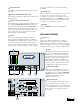
DX810 Digital Audio Mixer/ Signal Processor Instruction Manual OL OL OL OL OL OL OL 2 4 7 10 15 20 25 30 35 40 50 2 4 7 10 15 20 25 30 35 40 50 2 4 7 10 15 20 25 30 35 40 50 2 4 7 10 15 20 25 30 35 40 50 2 4 7 10 15 20 25 30 35 40 50 2 4 7 10 15 20 25 30 35 40 50 2 4 7 10 15 20 25 30 35 40 50 OL 15 12 9 6 3 2 4 7 10 15 20 25 30 35 40 50 0 3 6 9 12 15 DX8 DIGITAL MIXER A 1 2 3 4 5 6 7 8 LO EQ HI A MASTER B LOCK MODE B POWER COMM PORT 1 2 3 4 5 6 7 8 SERIAL NUMBER MAN
CAUTION AVIS RISK OF ELECTRIC SHOCK DO NOT OPEN RISQUE DE CHOC ELECTRIQUE NE PAS OUVRIR CAUTION: TO REDUCE THE RISK OF ELECTRIC SHOCK DO NOT REMOVE COVER (OR BACK) NO USER-SERVICEABLE PARTS INSIDE REFER SERVICING TO QUALIFIED PERSONNEL ATTENTION: POUR EVITER LES RISQUES DE CHOC ELECTRIQUE, NE PAS ENLEVER LE COUVERCLE. AUCUN ENTRETIEN DE PIECES INTERIEURES PAR L'USAGER. CONFIER L'ENTRETIEN AU PERSONNEL QUALIFIE.
2. INTRODUCTION The DX810 is our popular DX8 stereo digital audio mixer with the DX10e Expansion Kit installed. This adds eight more balanced outputs and converts it into a powerful matrix mixer/processor. It is designed for use in a variety of installations such as churches, courtrooms, convention centers, and hotels. With eight inputs, ten outputs, and a toolbox full of DSP, the DX810 fits most any installed sound reinforcement application.
• 2-band sweepable shelving EQ with a parametric mid on each Input FRONT PANEL FEATURES • Gating on each Input • 31-band Graphic EQ on each Output • 5-band Parametric EQ on each Output Note: The front panel controls only apply to the A and B outputs. Outputs C through J are controlled with the DX-10E-PC software interface.
17 for more information on locking and unlocking the DX810. EQ LED DISPLAY This display is disabled in the DX810 (it is for DX8 use only). MASTER A/B UP/DOWN BUTTONS These buttons adjust the output level for the A and B output buses. MASTER OUTPUT LED DISPLAY This indicates the signal level after the digital signal processing and MASTER A and B gain stage, just prior to the D/A converter. When any MASTER UP/ DOWN button is pressed, all the meters switch from level metering to level setting indication.
of each logic input and output can be programmed via software to suit individual applications. See page 13 for the Logic I/O pinouts. BUS A and B TRIM These rotary analog controls are used to trim the gain of the inputs to the A and B buses. This trim control provides from –20 dB to +20 dB of gain, with unity (0 dB) at the center-detent position.
4-Track Recorder LISTED COMMERCIAL AUDIO EQUIPMENT 9Z39 , 50/60Hz, 1A MAX Mix Minus Outputs R 100 – 240V – + THE FOLLOWING ARE TRADEMARKS OR REGISTERED TRADEMARKS OF MACKIE DESIGNS INC "MACKIE", "MACKIE INDUSTRIAL", AND THE "RUNNING MAN" FIGURE CONCEIVED, DESIGNED, AND MANUFACTURED BY MACKIE DESIGNS INC WOODINVILLE • WA • USA MADE IN USA • FABRIQUE AU USA • COPYRIGHT ©1999 24VDC Power Supply POWER INPUT 22-28V DC, 3A MAX +20 U LINE LINE + G – MIC + G – BUS A TRIM -20 +20 U 1 LINE MIC
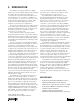
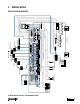
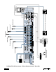
B: Typical Community Center Application DX810 – 8 – Music On Hold 24VDC Power Supply –10 –8 –6 –3 0 – 5 – 10 – 15 – 20 – 25 – 30 – 40 R 100 – 240V – + LINE – MIC + G LINE G + – BUS A M1400i POWER INPUT 22-28V DC, 3A MAX +20 U +20 LINE TRIM –10 –8 –6 –3 0 – 5 – 10 – 15 – 20 – 25 – 30 – 40 BUS B -20 U DIRECT OUTPUTS 1 2 3 4 5 6 7 8 TRIM -20 Gymnasium Two-Way Stereo System M1400i LISTED COMMERCIAL AUDIO EQUIPMENT 9Z39 , 50/60Hz, 1A MAX THE FOLLOWING ARE TRADEMARKS OR REGISTERED
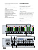
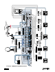
C: DX810 in Church Application DX810 – 9 – 24VDC Power Supply –10 –8 –6 –3 0 – 5 – 10 – 15 – 20 – 25 – 30 – 40 PA121 R 100 – 240V PA121 M1400i LISTED COMMERCIAL AUDIO EQUIPMENT 9Z39 , 50/60Hz, 1A MAX – + THE FOLLOWING ARE TRADEMARKS OR REGISTERED TRADEMARKS OF MACKIE DESIGNS INC "MACKIE", "MACKIE INDUSTRIAL", AND THE "RUNNING MAN" FIGURE CONCEIVED, DESIGNED, AND MANUFACTURED BY MACKIE DESIGNS INC WOODINVILLE • WA • USA MADE IN USA • FABRIQUE AU USA • COPYRIGHT ©1999 + G LINE LINE + – PA18
D: DX810/DX-10E Application : 8-Track Recording with 2-Track Mix DX810 – 10 – 24VDC Power Supply LISTED COMMERCIAL AUDIO EQUIPMENT 9Z39 , 50/60Hz, 1A MAX – + POWER INPUT 22-28V DC, 3A MAX +20 LINE LINE + G – MIC + G – BUS A TRIM -20 U LINE TRIM +20 BUS B -20 U DIRECT OUTPUTS 1 2 3 4 5 6 7 8 Monitor 2-track mix through phones connected to 2-track recorder.
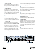
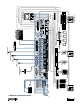
Applications A: DX-810 Application: Courtroom System This example employs seven microphones connected to the MIC inputs of the DX810. All microphones in all examples can be any combination of dynamic and/or condensor microphones. Phantom Power is selected for the appropriate inputs that use condensor microphones. This applies to all the following examples also. A cassette tape playback signal is routed to Input 8. A 4-track recorder taps off of four of the input signals via the DIRECT OUTPUTS jack.
Connections DIRECT OUTPUTS SIGNAL RETURN SIGNAL RETURN SIGNAL RETURN SIGNAL RETURN SIGNAL RETURN SIGNAL RETURN SIGNAL RETURN Connecting Balanced Sources Use high-quality three-conductor cable for balanced connections, such as Star Quad by Belden, Canare, or Mogami, etc. The better the shield, the better the audio signal is protected from induced EMI and RFI. Note: With screw-down connectors, it's best to use stranded wire that is not tinned.
Connecting the LOGIC I/O This is a 25-pin D-Sub connector. There are 10 logic inputs and 10 logic outputs. They are all active-low circuits. Use 22 gauge wire for these connections. Note: Pins 12, 13, and 24 are not used at this time. They are reserved for future updates. Do not connect anything to these pins.
4. OPERATION Quick Start Reading the instruction manual is the only way to fully understand the features and functions of the DX810. However, this Quick Start section provides a quick overview to get the DX810 set up and working fast. Make sure the power switch is off while setting up and making connections to the DX810. Make the Connections MIC Determine which inputs to use for – + G program sources and which to use for microphones. Follow the wiring diagram on the rear panel to make the connections.
Using Inputs 1-8 Bus A and B Input Trim There is no metering after the BUS A and B input TRIM controls. These controls must be adjusted by ear. Start the program source playback for all sources connected to the BUS A or BUS B input. Slowly increase the TRIM control to the center position (12 o'clock), which is unity gain. Then adjust the TRIM control up or down to attain a balance within the total mix at the A and B outputs.
Using the BUS A and B Inputs These inputs provide a direct analog connection to the BUS A and B buses. These input points are post-DSP and post-D/A converter, and accept a balanced analog line-level signal. Use these to connect an additional program source to a zone, or to connect the Zone A and B outputs from another DX810. This remote device is designed to select functions such as preset selection, mute, and forceon/off.
unconnected or inactive, the logic voltage level is high (+5 V). The active state is defined as voltage low (0 V or ground). The logic functions assigned to each individual logic input and output are configured using the DX-10E-PC application. In addition, each logic input and output can be assigned a descriptive name (up to 32 characters) for easier identification within the PC application. Note: Logic I/O functions are set from the PC only.
5. DX-10E-PC SOFTWARE (v 1.11) Installing the Software Connecting a PC A PC-based Windows-style graphical interface software application is provided on a CD-ROM. This is to control and configure the DX810 at the point of installation. Check our website at www.mackieindustrial.com/Downloads/ Downloads.html for software upgrades as they become available. Use a standard DB9 (male/female) computer cable to connect a PC to the DX810. The DX-10E PC application uses COM1 on the PC by default.
Caution: To adjust a fader, click on the fader knob to select it. If you click above or below the knob, it will jump to the point where you clicked. This is useful to move the fader quickly to where you want it to be. However, be careful not to inadvertently click above a fader knob. A sudden jump in volume will occur. Edit Top Section The Top Section includes the Menu bar, the Active Logic Input and Output indicators, and Preset, On Line, and Panel Lock controls.
Firmware Upgrade This allows you to select an OS upgrade file to upload to the DX-10E as they become available. Click Select File in the Firmware Upgrade window and the Select OS Upgrade File dialog box opens. Browse to the location of the OS upgrade file (with a .pkt extension) on your hard drive or floppy drive and click Open, then click Upgrade. You can monitor the progress in the Firmware Upgrade window. Set Lock Code Select this to view and change the four-digit locking code for the DX810.
About XOver This provides information about the DX–10E–PC software application, including the version and personnel credits. This toggles the Crossover window open and closed. It duplicates the function of the X-Over button in the Button Section. Options The Options window is reserved for future upgrades. Audio Input This toggles the Audio Input window open and closed. It duplicates the function of the Audio In button in the Button Section.