
- MACKIE Instruction Manual Digital Audio Mixer/ Signal Processor DX810

DX810 – 5
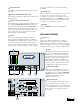
EQ LED DISPLAY
This display is disabled in the DX810 (it is for DX8
use only).
MASTER A/B UP/DOWN BUTTONS
These buttons adjust the output level for the A and
B output buses.
MASTER OUTPUT LED DISPLAY
This indicates the signal level after the digital signal
processing and
MASTER A and B
gain stage, just
prior to the D/A converter. When any
MASTER
UP/
DOWN button is pressed, all the meters switch
from level metering to level setting indication. After
five seconds, the meters switch back to normal
peak program metering (PPM).
MODE
This switch changes the front panel operation
between Bus A and Bus B operation. In addition,
the
LOCK
position disables the front panel controls
to prevent unauthorized changes to the settings. A
security code must be entered to enable the front
panel controls when the DX810 is locked. See page
17 for more information on locking and unlocking
the DX810.
COMM PORT
This is an RS-232 port on a 9-pin D-Sub connector.
It connects to a personal computer or other
compatible control system for external control of
the DX810 settings. A second
COMM
port on the
rear panel duplicates this function, for permanent
connection to an installed controller.
POWER
Use the
POWER
switch to turn the DX810 on
and off.
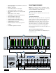
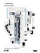
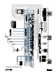
REAR PANEL FEATURES
INPUTS 1-8
Each of the eight analog inputs has separate
balanced mic and line input connectors that use
Mackie’s acclaimed XDR mic preamps. These are
3-pin Phoenix-type connectors. Use either the
MIC
or
LINE
input, but only one can be used per channel.
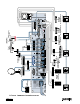
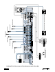
TRIM
This rotary analog control is used to trim
the gain of the input signal for optimum
signal-to-noise ratio in the preamp stage.
For mic-level signals, it provides from 0 to
+60 dB of gain. For line-level signals, it
provides from –30 dB to +30 dB of gain.
Unity (0 dB) is at the center position. This
control accepts a maximum input signal of
+18 dBu before clipping (at unity gain).
PHANTOM POWER
These switches apply phantom power
(+48 VDC) to pins 2 and 3 of the selected
mic input connectors. Put the
PHANTOM
POWER
switch in the UP position for an
individual channel when using a
condenser microphone.
BUS A/B INPUTS
These analog inputs accept balanced line-
level signals and route the signal to the
internal A and B buses. These inputs may
serve as additional zone inputs for program
devices. There is no DSP processing on
these inputs.
2
OL
4
7
10
15
20
25
30
35
40
50
A B LOCK
MODE
POWER
COMM PORT
BA MASTER
DX8 DIGITAL MIXER
B
REMOTE BUS
A
RECORD
A
B
OUTPUTS
LOGIC I/O
TRIM
8
M
I
C
G
A
I
N
0
60
T
URING DATE
COMM PORT
12345678
LINE
MIC
-
30dB +30dB
U
N
0
0
dB
PHANTOM POWER
48V DC
12 1 +5V
11G
1
G
+
–
G
+
–
G
+
–
INPUTS
OUTPUTS
ON
J I H G
C D E F
•
10
e
–
+
G
G
+
–