TM MultiView II DVI-Tx Transmitter Installation and User Guide Version 1.00 2791 Circleport Drive, Erlanger, KY 41018, USA. Americas: 859-282-7303 EMEA: +44 (0) 1843 873322 Email: tech.usa@tvone.com www.tvone.
Manual Copyright Notice This document and the Magenta Research products to which it relates, and the copyright in each, is the intellectual property of tvONE, ©2014. Neither the document nor the products may be reproduced by any means, in whole or in part, without the express prior written permission of tvONE.
Regulatory Compliance Statements FEDERAL COMMUNICATIONS COMMISSION AND INDUSTRY CANADA RADIO FREQUENCY INTERFERENCE STATEMENTS This device complies with part 15 of the FCC Rules. Operation is subject to the following two conditions: 1. This device may not cause harmful interference, and 2. This device must accept any interference received, including interference that may cause undesired operation.
Precautions Precautions Safety Instructions ● English This symbol calls attention to important information. This symbol alerts the user of important maintenance (or servicing) and operating information. This symbol alerts the user to the presence of un-insulated dangerous voltages or other conditions in, or around, the product enclosure. These conditions can present a risk of electric shock or damage to equipment or facilities.
Precautions Table of Contents Page Chapter 1 Specifications ............................................................................................................................. 1 1.1 DVI Interface ................................................................................................................... 1 1.2 DDC/EDID Support ......................................................................................................... 2 1.3 Auxiliary Signal Support ............................
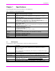
Specifications Chapter 1 Specifications The following table lists the general specifications of the MVII-DVI-Tx. Table 1: MVII-DVI-Tx General Specifications Item Description UTP Cable Required Supported Video Formats Audio Signals Serial Characteristics Connectors Temperature/Humidity Tolerance Enclosure Power Size Weight 1.1 4 twisted-pair “FTP” type cable is recommended for performance and EMC compliance. Regular or minimized-skew type is acceptable.
Specifications 1.2 DDC/EDID Support For best compatibility with source devices (eg, a PC), an extension device (DVI-Tx in this case) should provide an appropriate DDC/EDID profile with the proper resolution and timing information to that source device. This helps ensure best compatibility with display devices connected at the remote end. The DVI-Tx is factory-programmed with a fixed EDID table. The supported video formats are detailed in Appendix-A.
Specifications 1.3.2 Auxiliary Signal support: SAP version The MVII DVI-Tx-SAP comes equipped with an internal hardware SAP option module, enabling full-duplex RS232 serial (no hardware handshaking signals) and stereo audio. The SAP module in the DVI-Tx has no address-switch settings. However, it is important to check the address-switch settings in the connected Receiver SAP units (DVI-Rx-1K-SAP, AK600/1200DP-SAP etc.).
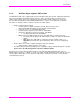
About this Manual Chapter 2 About this Manual This manual describes the Magenta MultiView™ II DVI-Tx transmitter, and contains the following information: Specifications (Chapter 1) Product Overview (Chapter 3) Twisted-pair Cable Compatibility (Chapter 4) Installation (Chapter 5) Troubleshooting (Chapter 6) Connector pinouts (Chapter 7) Additional information (Appendices) The Magenta MultiView™ II family (MVII) of products introduces greater compatibility for handling HD video standards, a
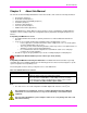
Product Overview Chapter 3 Product Overview The MVII-DVI-Tx is a video transmitter that is compatible with the MVII-DVI-Rx-1K receiver, and many legacy MultiView products – contact Technical Support with compatibility questions. It extends a digital video signal over standard twisted-pair “FTP” type cable. There are user-configurable settings for video, audio, and serial options which can be controlled from the front panel.
Product Overview 3.
Twisted-pair Cable Compatibility Chapter 4 Twisted-pair Cable Compatibility The MVII-DVI-Tx transmitter is compatible with twisted-pair “FTP” type cable. This type of cable ensures best possible product performance, and maintains EMC compliance for emissions and susceptibility. However, in applications that must use cable other than “FTP”, it is up to the end-user to ensure product performance at the intended resolution and distance, and that additional steps are taken to mitigate any RF interference.
Installation Chapter 5 Installation This section describes the following installation topics: Data mode configuration Prerequisites to installation Installation procedure Post-installation adjustments Post-installation configuration settings This equipment is not intended for, nor does it support, distribution through an Ethernet network. Do not connect these devices to any sort of networking or telecommunications equipment! Do not connect DC power until instructed to do so. 5.
Installation To install a MultiView-II DVI-Tx transmitter: 1. Connect the source video to the Magenta MultiView™ DVI-Tx transmitter’s video input port, which is a DVI-D connector labeled DVI-IN. 2. If desired, attach a local monitor to the DVI-D connector labeled LOCAL OUT (if available). 3. Make your audio or serial connections via the AUX-I/O (Phoenix) connector or DB9 connector as appropriate. 4. Connect the twisted-pair cable to the transmitter. 5. Apply power to the transmitter. a.
Installation To install the MVII-DVI-Rx-1K receiver: 1. Connect the DVI OUT connector to the display. 2. Connect any audio and/or serial cables to the (AUX I/O) and (IOIO) connectors, depending on the specific model of receiver you are installing. Please refer to the –A, -S or –SAP option descriptions for more information. 3. Connect the twisted-pair cable from a MultiView-II™ DVI-Tx transmitter to the LINK INPUT connector on the receiver. 4.
Installation 5.4 Adjustments This section describes how to make the following adjustments: Cable distance (EQ) compensation Skew compensation Note that the factory-default behavior of the MVII-DVI-Rx-1K “auto-adjust mode enabled” for the EQ and skewcomp. To exit auto-adjust mode, simply attempt to make a manual adjustment to either EQ or Skew. To re-enable auto-adjust mode, simply push both UP and DOWN buttons simultaneously when the receiver is operating in “normal mode”. 5.
Installation 5.6 Skew Compensation Settings The AkuComp-II skew module is already included inside the standard MVII-DVI-Rx-1K receiver. It is possible to quickly adjust the RGB skew-compensation values when the receiver is operating in normal mode. The EQ/SKEW indicators 1-8 will change accordingly to show (in “bar-graph” form) 0 to 100% of the available SKEW adjustment range (0 to 65nSec). For best results, use the Magenta EQ/Skew test pattern image if possible.
Installation 5.7 Configuration The DVI-Tx has a number of configurable operating parameters, and the factory-default settings will work in most applications. However, some applications may require configuration changes. Nearly all settings are available from the front-panel buttons/LEDs. The enclosure does not need to be opened unless the SAP option module is being installed or removed. For all configuration settings, the DVI-TX must be in CONFIG mode (CFG indicator is on).
Installation 5.7.1 Sync Settings The DVI-Tx supports the complete set of MultiView sync modes: RepliSync-I, RespliSync-Ia (normal/stretched): Generally needed for legacy MultiView receivers. RepliSync-II: Required for newer MultiView-II receivers. Auto-detect RSI/RSIa: The DVI-Tx will automatically select RepliSync-I or RepliSync-II, depending on video format. Fixed-Sync: Necessary for some legacy receivers and VGA displays.
Installation 5.7.2 4th Pair Settings The DVI-Tx provides several options for using the 4th-pair signals (pairs 1-3 are generally used for video). Note that any connected MultiView™ receiver must be configured with a matching 4th-pair operating mode. Otherwise, the desired 4th-pair signal will not work as expected. If the optional SAP daughterboard is installed, then the 4th-pair utilization is defined by the installed daughterboard.
Troubleshooting Chapter 6 Troubleshooting In most cases, nearly every issue with the MultiView™ video system can be resolved by checking the twistedpair cable termination and making sure that it’s pinned to the TIA/EIA 568B wiring specification. However, there may be other problems that cause the system to not perform as it’s designed. The following table lists the most common installation errors and their solutions.
Connector Pinouts Chapter 7 Connector Pinouts DVI-D connector pinout: Pins #1-8 Key holes, to prevent wrong type of cable being plugged in Pins #9-16 Pins #17-24 DVI (Digital Visual Interface) is a robust and popular video interface standard that can include digital and analog options in the same connector (the “DVI-I” version). However, as the MVII-DVI-Tx is a digital-video only device, it supports the “DVI-D” subset of the DVI standard interface.
Connector Pinouts Auxiliary I/O (AUX-I/O) Connector Pinout Pin #1 Pin #4 Figure 7: 4-pin Phoenix Connector Pinout Table 4: Auxiliary I/O (4-pin Phoenix) Pin Usage (S) (A) (SAP) SPDIF PIN# Simplex Audio Audio Audio Serial 1 Left Left Tx Signal + (SIG1) Channel Channel 2 Ground Ground ground Signal (GND) 3 Right Right (SIG2) Channel Channel 4 Shell (GND) MultiView™ II DVI-Tx Installation and User Guide 18
Connector Pinouts Serial port (IOIO) connector pinout (SAP version only): The DVI-Tx’s serial port connector is configured to look like a standard 9-pin “DCE” serial port. Therefore, in most applications a straight through serial cable or adapter-plug (DB9-Female-toMale) is used to connect an external serial device (for example, a PC) to the DVI-TX transmitter. Pin #5 Pin #1 Pin #9 Pin #6 DB9-F Serial Port The DB9-F serial port is only available on DVI-TX-SAP model.
Connector Pinouts RJ45 (MultiView Link) Wiring Standard Figure 8: T568B Category Cable Wiring Standard Table 5: T568B wiring for RJ-45 plug PIN # COLOR PAIR 1 White / Orange Stripe 2 2 Orange Solid 2 3 White / Green Stripe 3 4 Blue Solid 1 5 White / Blue Stripe 1 6 Green Solid 3 7 White / Brown Stripe 4 8 Brown Solid 4 Pins on plug face (socket is reversed) Figure 9: Typical RJ-45 Plug MultiView™ II DVI-Tx Installation and User Guide 20
Connector Pinouts DC Power Connector Magenta provides ready-to-use power supplies for MultiView™ II products. However, if there is a reason a substitute power supply must be used, then the following information is important for maintaining product reliability and performance: Magenta AC/DC Power supply output rating: Regulated +5VDC @ 2.6Amps. Power-input rating for MVII-DVI-Tx: 5VDC, 1.2Amps max.
Supported Video Formats and Features Appendix A Supported Video Formats and Features The following video formats are supported by the MVII-DVI-Tx and MVII-DVI-Rx-1K (combined) link. Note that while the MVII-DVI-Tx can be used as a source for other types of MultiView receivers with VGA outputs (for example, MVII-AK600DP), not every video format is guaranteed to work with any particular display. Success greatly depends on the display’s internal VGA-scaler hardware.
(SAP) Option Module Settings Appendix B (SAP) Option Module Settings The SAP option module allows a bi-directional session to be established between a SAP-equipped transmitter (MVII-DVI-Tx-SAP), and a specific SAP-equipped receiver even in a multiple-receiver daisy chain installation. The SAP transmitter devices (MVII-DVI-Tx-SAP for example) do not have address DIP-switches. The factorydefault address of the transmitter is “0”.
Pollable Serial Mode Address Chart Appendix C ADDR 00 01 02 03 04 05 06 07 08 09 10 11 12 13 14 15 16 17 18 19 20 21 22 23 24 25 26 27 28 29 30 31 Pollable Serial Mode Address Chart Switch Settings 1 ADDR 2 3 4 5 6 7 8 2 3 4 5 6 7 8 1 2 1 1 3 4 5 6 7 8 2 3 4 5 6 7 8 3 1 2 1 4 2 4 2 3 2 3 1 1 5 6 7 8 3 4 4 5 5 5 6 6 6 7 7 7 8 8 8 4 1 2 3 1 2 3 2 1 1 5 5 3 2 8 6 7 8 5 6 7 8 4 5 3 4 3 4 2 3 4 2 3 4 2 1 5 2 5 1 1 7 4 3 1 6
Pollable Serial Mode Address Chart SAP Addressing chart, cont’d: ADDR 128 129 130 131 132 133 134 135 136 137 138 139 140 141 142 143 144 145 146 147 148 149 150 151 152 153 154 155 156 157 158 159 Switch Settings ADDR 8 1 2 3 4 5 6 7 2 3 4 5 6 7 3 4 5 6 7 3 4 5 6 7 4 5 6 7 4 5 6 7 4 5 6 7 4 5 6 7 5 6 7 5 6 7 5 6 7 5 6 7 5 6 7 5 6 7 5 6 7 5 6 7 6 7 6 7 6 7 6 7 6 7 6 7 6 7 6 7 6 7 6 7 6 7 6 7 6 7 6 7 6 7 6 7
Mounting Kits Appendix D Mounting Kits There are several kits available for mounting the DVI-TX: Mounting Kit # 2211053-01 Description Rigid-mount bracket. This mounts a single device to a surface (wall/desk/etc.). Comes with 4 self-tapping screws. 8310207-01 1U Rack-mount Plate for standard 19” rack. Mounts 4 devices in a 1U space. Comes with (8) device-mounting screws, (4) rack-mounting screws. 8310208-01 2U Rack-mount Plate for standard 19” rack. Mounts 8 devices in a 2U space.
Index About this manual, 4 Adjustments, 11 EQ setting, 11 Skew setting, 12 Auxiliary I/O connector, 18 Configuration 4th-pair Modes, 15 Factory defaults, 13 general, 13 Sync modes, 14 Connectors auxiliary I/O, 18 DC power, 21 DVI Port, 17 Link (RJ45), 20 Default Settings, 13 Front panel interfaces, 5 Installation, 8 prerequisites, 8 procedure, 8 SAP Module Configuration, 8 Mounting kits, 26 MultiView™ II DVI-Tx Installation and User Guide Option module settings SAP option module, 23 Pinouts Serial Port, 1
NOTES: MultiView™ II DVI-Tx Installation and User Guide 28
2791 Circleport Drive, Erlanger, KY 41018, USA. Americas: 859-282-7303 EMEA: +44 (0) 1843 873322 Email: tech.usa@tvone.com www.tvone.