MS Series Pure Sine Wave Inverter/Charger Owner’s Manual TM
Disclaimer of Liability Since the use of this manual and the conditions or methods of installation, operation, use and maintenance of the MS Series Inverter/Charger is beyond the control of Magnum Energy Inc., this company does not assume responsibility and expressly disclaims liability for loss, damage or expense, whether direct, indirect, consequential or incidental, arising out of or anyway connected with such installation, operation, use, or maintenance.
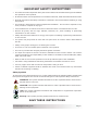
IMPORTANT SAFETY INSTRUCTIONS • This manual contains important safety instructions that must be followed during the installation and operation of this product. • All electrical work must be performed in accordance with local, state and federal electrical codes. • Read all instructions and safety information contained in this manual before installing or using this product. • This product is designed for indoor/compartment installation.
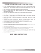
IMPORTANT BATTERY SAFETY INSTRUCTIONS • Be very careful when working around batteries, they can produce extremely high currents if short-circuited. Read the battery supplier’s precautions before installing the inverter and batteries. • Wear eye protection such as safety glasses when working with batteries. • Remove all jewelry such as rings, watches, bracelets, etc., when installing or performing maintenance on the inverter. • Never work alone.
Table of Contents 1.0 Introduction ..................................................................................1 2.0 Installation ...................................................................................7 3.0 Operation ....................................................................................39 4.0 Maintenance and Troubleshooting ...............................................46 1.1 1.2 1.3 1.4 2.1 2.2 2.3 2.4 2.5 2.6 2.7 2.8 2.9 3.1 3.2 3.3 3.4 3.5 3.6 3.7 3.8 4.1 4.
List of Figures Figure Figure Figure Figure Figure Figure Figure Figure Figure Figure Figure Figure Figure Figure Figure Figure Figure Figure Figure Figure Figure Figure Figure Figure Figure Figure Figure Figure Figure Figure Figure Figure Figure Figure Figure Figure Figure Figure Figure Figure Figure 1-1, Power Switch, Status LED and Accessory Connection Ports .................................................3 1-2, Electrical Connection Points ..............................................................
Introduction 1.0 Introduction Congratulations on your purchase of the MS Series inverter/charger from Magnum Energy. The MS Series is a “pure” sine wave inverter designed especially for rugged mobile applications, home backup power and stand-alone applications. Powerful, yet simple to use, this inverter/charger will provide you with years of trouble-free performance you have come to expect from Magnum Energy. Installation is easy.
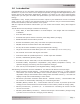
Introduction 1.1 Features and Benefits The MS Series inverter/charger is designed to allow easy access to wiring, circuit breakers, controls and for viewing the LED (Light Emitting Diode) status indicator. Its die cast base plate with one piece aluminum cover ensures maximum durability with minimum weight, as well as cooler more efficient operation.
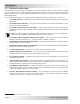
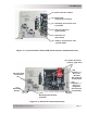
Introduction (1) Power ON/OFF Switch (2) Status LED (Charging/Inverting) (3) Stacking/Accessories Port (red label) (4) Magnum Net Port (green label) (5) Remote Port (blue label) (6) Battery Temp Sensor Port (yellow label) Figure 1-1, Power Switch, Status LED and Accessory Connection Ports (9) Intake Air Vents (and on right side) (10) Positive (+) DC Cover (Positive DC Terminal underneath) AC Entry/Exit Connections (8) (11) Negative (–) DC Cover (Negative DC Terminal underneath) (7) Mounting Flange (1
Introduction The left side of the MS Series is equipped with the following features (see to figure 1-3): • (13) Exhaust Air Vent - ventilation openings that allow heated air to be removed by the internal cooling fan. • (14) Model/Serial Number Label - includes model/serial number information, date of manufacture and inverter and charger specifications. See Appendix A for more information and to find the available models.
Introduction 1.2 How an Inverter/Charger Works There are two modes of operation associated with this inverter/charger: • Inverter Mode: When the inverter is properly connected to batteries and turned on, the Direct Current (DC) from the batteries is transformed into a pure sine wave Alternating Current (AC). This AC is similar to the voltage provided by your utility and is used to power the electrical appliances (i.e. AC loads) connected to the inverter’s output.
Introduction 1.4 Appliances and Run Time The MS Series inverter/charger can power a wide range of household appliances including small motors, hair dryers, clocks and other electrical devices. As with any appliance using batteries for power, there is a certain length of time that it can run - this is called “run time.” Actual run time depends on several variables including the size and the type of appliance, the type of batteries installed in your application, as well as the battery’s capacity and age.
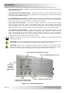
Installation 2.0 Installation Info: Installations should be performed by qualified personnel, such as a licensed or certified electrician. It is the installer’s responsibility to determine which safety codes apply and to ensure that all applicable installation requirements are followed. Applicable installation codes vary depending on the specific location and application of the installation.
Installation G e n e ra to r P o w e r 1 2 0/2 4 0 V A C O u tp u t U tility P o w e r 1 2 0/2 4 0 V A C O u tp u t F ul x AC T ra n s fe r S w itc h C a pa c oti r M E -A G S - N A u to G en S tart C o n tro ller (M ag n u m O p tio n ) G e ne ra t or P WR FA U LT S E L E CT C H G IN V ON / OF F CHARG ER ON / OF F I NVERTER SHO RE AG S M ETER SETUP TECH M E -R C 50 R em o te C o n tro l (M ag n u m O p tio n ) M a in P a n e l O FF OF F OF F O FF OF F OF F ON ON ON ON O FF OF F O F
Installation 2.1.3 Locating the Inverter Only install the inverter in a location that meets the following requirements: Clean and Dry - The inverter should not be installed in an area that allows dust, fumes, insects or rodents to enter or block the inverter’s ventilation openings. This area also must be free from any risk of condensation, water or any other liquid that can enter or fall on the inverter.
Installation 2.2 Mounting the Inverter The inverter base can reach a temperature up to 90°C (194°F), and it is recommended that it should be mounted on a noncombustible surface*. This surface and the mounting hardware must also be capable of supporting at least twice the weight of the inverter.
Installation 8" 6 5/8" 12" Keyhole slots (x4) and mounting holes (x4) accept up to 9/32" screw/ bolt 13 3/4" 4 7/8" 2" 4 7/8" 12 5/8" Figure 2-3, MS Series Dimensions © 2009 Magnum Energy Inc.
Installation 2.3 Wiring the Inverter - General Requirements This section also describes the requirements and recommendations for wiring the MS Series inverter/charger. Before wiring the MS Series inverter/charger, read all instructions. All wiring should meet all local codes and standards and be performed by qualified personnel such as a licensed electrician.
Installation 2.4 DC Wiring This section describes the inverter’s required DC wire sizes and the recommended disconnect/ overcurrent protection and how to make the DC connections to the inverter and the battery bank. Refer to figure 2-4 when connecting the DC wires. WARNING: Even though DC voltage is “low voltage”, significant hazards may be present, particularly from short circuits of the battery system.
Installation M S S e rie s In v e rte r/C h a rg e r w all m ounted view front view M E-CB Conduit Box Inv e rte r’s D C P os itiv e C a ble Inv e rte r’s D C N e ga tiv e C a ble B a tte ry Te m p S e ns or C a ble Inv e rte r’s D C E quipm e nt G round W ire DC Circuit Breaker Box D C O v e rc urre nt P rote c tion (C irc uit B re a k e r or Fus e /s w itc h ) DC S hunt D C N e ga tiv e To D C G round J um pe r D C G round B us -ba r Battery Bank D C G rounding point [V e hic le c ha s s is , E le
Installation 2.4.1 DC Wire Sizing It is important to use the correct DC wire to achieve maximum efficiency from the system and reduce fire hazards associated with overheating. Always keep your wire runs as short as practical to help prevent low voltage shutdowns and keep the DC breaker from nuisance tripping (or open fuses) because of increased current draw. See Table 2-1 to select the minimum DC wire size (and corresponding overcurrent device) required based on your inverter model.
Installation Table 2-2, DC Wire Size For Increased Distance Inverter Model Minimum Recommended DC Wire Size (one way)* 5 feet or less In Conduit 5 to 10 feet In free air In Conduit 10 to 15 feet In free air In Conduit In free air #4/0 AWG x2 MS2012 #4/0 AWG #2/0 AWG #4/0 AWG x2 #4/0 AWG not recommended MS2812 #4/0 AWG #4/0 AWG #4/0 AWG x2 #4/0 AWG x2 not recommended not recommended MS4024 #4/0 AWG #2/0 AWG #4/0 AWG x2 #4/0 AWG not recommended #4/0 AWG x2 * Copper wire rated with
Installation 2.4.4 Wiring the DC Overcurrent Protection Device A fuse/disconnect or circuit breaker must be provided in the DC positive line between the battery and the inverter to protect the DC wiring system. Mount the fuse block (or circuit breaker assembly) as near as practical to the batteries. For maximum protection, install it within 18 inches (45 cm) of the battery. 1.
Installation 2.4.6 Battery Temperature Sensor Installation and Wiring The Battery Temperature Sensor (shown in figure 2-7) provides the inverter with precise battery temperature information to automatically adjust the ABSORB and FLOAT charge voltage setpoints This allows the batteries to be correctly charged under extreme temperature changes. If the temperature sensor is NOT installed and if the batteries are subjected to large temperature changes, the battery life may be shortened.
Installation 2.4.7 Wiring the Inverter to the Battery Bank CAUTION: Inverter is NOT reverse polarity protected, if this happens the inverter will be damaged and will not be covered under warranty. Before connecting the DC wires from the batteries to the inverter, verify the correct battery voltage and polarity using a voltmeter. If the positive terminal of the battery is connected to the negative terminal of the inverter and vice versa, severe damage will result.
Installation 2.5 AC Wiring This section provides information on how to make the AC connections to the inverter using the correct AC wire size and corresponding overcurrent protection. 2.5.
Installation AC Input Strain Relief Clamp AC Output Strain Relief Clamp Figure 2-8, MS Series Inverter/Charger - AC Wiring AC Access Panel AC Input Circuit Breaker (CB3) AC Output 2 Circuit Breaker (CB2) (on -15B, -20B output breaker models only) AC Output 1 Circuit Breaker (CB1) (on -15B, -20B output breaker models only) Figure 2-9, MS Series Inverter/Charger - AC Wiring (Access Panel) © 2009 Magnum Energy Inc.
Installation 2.5.3 Recommended GFCI (Ground Fault Circuit Interruption) Breakers Some electrical safety codes require the use of GFCI’s. In compliance with UL standards, Magnum Energy has tested the following GFCI’s and find that they function properly when connected to the inverter’s AC output: Shock SentryTM #XGF15V-SP Leviton Smart Lock #8899-A Hubbel #GF520EMBKA 2.5.
Installation 2.5.5 AC Conductor Wiring The following steps are basic guidelines for installing and connecting the AC wiring into and out of the inverter, refer to table 2-3 to determine your AC wiring configurations before beginning. WARNING: Before making any AC connections, make sure the inverter is disconnected from the battery and all AC power is disconnected from the inverter. Wiring the Inverter AC Input 1.
Installation 2.5.5 AC Wiring Configurations The following table provides the different wiring configurations for installing and connecting the AC conductors into and out of the inverter (refer to figures 2-11 to 2-15 for installation drawings showing these configurations).
Installation A C T e rm in a l B lo c k ( A C in p u t a n d o u tp u t w irin g ) A C N E U T IN ( from M a in P a nel) A C H O T 1 IN ( from M a in P a nel) A C H OT 1 OU T (to S ub P ane l) A C N EU T O U T (to S ub P ane l) M S S e rie s In v e rte r AC G RO UNDS (to /from both P a ne ls) S IN G L E IN / S IN G L E O U T (3 0A ) w irin g In M obile installations : neutral is typically not connected to ground In m ain panel.
Installation A C T e rm in a l B lo c k ( A C in p u t a n d o u tp u t w irin g ) A C N E U T IN ( from M a in P a nel) A C H O T 1 IN ( from M a in P a nel) A C H O T 2 IN ( from M a in P a nel) A C H OT 1 OU T (to S ub P ane l) A C H OT 2 OU T (to S ub P ane l) A C N EU T O U T (to S ub P ane l) M S S e rie s In v e rte r AC G RO UNDS (to /from both P a ne ls) S IN G L E IN / S IN G L E O U T (6 0A ) w irin g In M obile installations : neutral is typically not connected to ground In m ain panel
Installation A C T e rm in a l B lo c k ( A C in p u t a n d o u tp u t w irin g ) A C N E U T IN ( from M a in P a nel) A C H O T 1 IN ( from M a in P a nel) A C H O T 2 IN ( from M a in P a nel) A C H OT 1 OU T A C H OT 2 OU T A C N EU T O U T (x2 ) M S 2 0 1 2- 1 5 B o r M S 2 0 1 2 -2 0 B In v e rte r AC G RO UNDS (to /from both P a ne ls) S IN G L E IN / D U A L O U T w irin g In M obile installations : neutral is typically not connected to ground In m ain panel.
Installation A C T e rm in a l B lo c k ( A C in p u t a n d o u tp u t w irin g ) A C N E U T IN ( from M a in P a nel) A C H O T 1 IN ( from M a in P a nel) A C H O T 2 IN ( from M a in P a nel) A C H OT 1 OU T (to S ub P ane l) A C N EU T O U T (to S ub P ane l) M S S e rie s In v e rte r AC G RO UNDS (to /from both P a ne ls) D U A L IN / S IN G L E O U T w irin g In M obile installations : neutral is typically not connected to ground In m ain panel.
Installation A C T e rm in a l B lo c k ( A C in p u t a n d o u tp u t w irin g ) A C N E U T IN ( from M a in P a nel) A C H O T 1 IN ( from M a in P a nel) A C H O T 2 IN ( from M a in P a nel) A C H OT 1 OU T (to S ub P ane l) A C N EU T O U T (to S ub P ane l) A C H OT 2 OU T (to S ub P ane l) M S S e rie s In v e rte r AC G RO UNDS (to /from both P a ne ls) D U A L IN / D U A L O U T w irin g In M obile installations : neutral is typically not connected to ground In m ain panel.
Installation 2.6 Grounding Inverters The inverter/charger should always be connected to a permanent, grounded wiring system. An inverter system that is properly grounded will limit the risk of electrical shock, reduce radio frequency noise from the inverter and minimize excessive surge voltages induced by lightning. This is done by ensuring there is a well-defined, very low-resistance path from the electrical system to the grounding system.
Installation 2.6.1 Sizing the Grounding Electrode Conductors AC Side - The size of the AC Grounding Electrode Conductor (GEC –AC) depends on the size of the largest ungrounded conductor feeding the AC load center. One #8 AWG (8.4 mm2) copper conductor will serve as an AC Grounding Electrode Conductor (GEC –AC) for AC power conductors smaller than and including #2 AWG (33.6 mm2) copper. See Table 2-4 for additional values.
Installation Method 2 (see figure 2-18): When the AC and DC service panels are near each other, then the AC Grounding Electrode Conductor (GEC – AC) and DC Grounding Electrode Conductor (GEC – DC) can be connected to a single Grounding Electrode. In this method - since there are multiple connections to the DC Grounding Electrode (GEC – DC) - the size of the DC Grounding Electrode Conductor can not be smaller than the largest conductor in the DC system (usually the batteryto-inverter cable).
Installation 2.6.2 System Bonding Jumper The MS Series inverter does not include an internal bond between the Grounded Conductor (AC neutral/DC negative) and the equipment grounding terminals. This bond [System Bonding Jumper (SBJ)] is usually done in the main distribution panel for each electrical system. CAUTION: There should be one and only one point in each electrical system (both AC and DC) where the Grounded Conductor is attached to the Grounding Electrode Conductor.
Installation 2.6.4 Grounding on Boats When installing the MS Series inverter/charger on a boat, there are several considerations that must be followed when grounding to ensure a safe installation, prevent galvanic corrosion and adhere to ABYC (American Boat and Yacht Council) standards. Ensure a Safe Ground Connection When AC on the boat is being supplied by shore power, the onboard neutral should be connected to safety ground on the dock.
Installation 2.6.5 Neutral to Safety Ground Bonding The standards for safely wiring residential, commercial, RV/truck and marine installations in the United States require the neutral and safety ground be connected at the AC source; whether it is the utility feed in your home, an inverter, or a generator. This is to establish a specification that maximizes the possibility that a circuit breaker will activate if a hot-wire-to-ground fault occurs.
Installation 2.6.6 Disabling the Neutral-to-Ground Connection All MS Series Inverter/Chargers have the automatic neutral-to-ground switching feature. In some installations/jurisdictions, this feature must be disabled. If you are not sure whether you must disable this feature, check your local code requirements. The following steps will guide you in disabling the neutral-to-ground switching feature in the MS Series inverter/charger.
Installation 2.7 Inverter Notification Requirements When an inverter is installed in a building, facility or structure, the NEC (National Electrical Code) requires a label or plaque to be provided. This label/plaque is required to be easily visible and provide information that informs personnel on the location of all electrical system disconnects. This is to ensure all power to a building is quickly located and shutdown in an emergency.
Installation 2.9 Functional Test After all electrical connections to the inverter, batteries, AC source, and sub-panel have been completed; follow these steps to test the installation and the inverter operation. CAUTION: Use a multimeter to verify the correct DC voltage for your particular inverter model (i.e.
Installation 3.0 Operation The MS Series inverter has two normal operating routines; 1. Inverter Mode, which powers your loads using the batteries, and 2. Standby Mode, which transfers the incoming AC Power (i.e., utility power or a generator) to power your loads and uses this incoming power to recharge the batteries. This inverter also includes an extensive protection circuitry to shut-down the inverter under certain fault conditions. 3.
Operation 3.2 Standby Mode The MS Series features an automatic transfer relay and an internal battery charger when operating in the Standby Mode. The Standby Mode begins whenever AC Power (Utility or Generator) is connected to the inverter’s AC input. Once the AC voltage and frequency of the incoming AC power is within the AC input limits, an automatic AC transfer relay is activated. This transfer relay passes the incoming AC power through the inverter to power the AC loads on the inverter’s output.
Operation The Charge Mode provides up to four separate charging stages: Bulk Charging, Absorb Charging, Float Charging and Full Charge. Bulk Charging: This is the initial stage of charging. While Bulk Charging, the charger supplies the battery with controlled constant current. The charger will remain in Bulk charge until the Absorption charge voltage (determined by the Battery Type selection*) is achieved. The inverter’s green LED stays ON (solid) to indicate Bulk charging.
Operation 3.4 Transfer Time While in the Standby Mode, the AC input is continually monitored. Whenever AC power falls below the VAC Dropout voltage (80 VAC, default setting), the inverter automatically transfers back to the Invert Mode with minimum interruption to your appliances - as long as the inverter is turned on. The transfer from Standby mode to Inverter mode occurs in approximately 16 milliseconds.
Operation 3.6 Protection Circuitry Operation The inverter is protected against fault conditions and in normal usage it will be rare to see any. However, if a condition occurs that is outside the inverter’s normal operating parameters, then it will shut down and attempt to protect itself, the battery bank, and your AC loads. If there is a condition that causes the inverter to shutdown, it may be one of the following conditions [also refer to the Troubleshooting section (Section 4.
Operation 3.7 Inverter Startup ON/OFF Switch - The inverter can be turned on and off by lightly pressing and releasing the Power ON/OFF switch on the front of the inverter (refer to figure 3-5). When the inverter is first connected to the batteries, or when its automatic protection circuit has turned the inverter off, the ON/OFF switch will need to be pressed to start the unit (or reset per section 4.4).
Operation 3.8 Factory Default Values Your MS Series inverter/charger uses default values for the adjustable settings (shown in Table 3-2) that are adequate for most installations. If some of your operating parameters need to be changed from the default values, the optional ME-RC remote control can be used to make those changes. To help you determine if you need the ME-RC remote display, information on the inverter/charger settings that can be changed is provided below.
Maintenance and Troubleshooting 4.0 Maintenance and Troubleshooting The following information is provided to help you keep your MS Series Inverter/Charger in optimum operational condition. 4.1 Recommended Inverter and Battery Care The MS Series inverter/ charger is designed to provide you with years of trouble-free service.
Maintenance and Troubleshooting 4.3 Troubleshooting The MS Series inverter/charger is a fairly simple device to troubleshoot. There are only two active circuits (AC and DC) as well as a charging circuit. The following chart is designed to help you quickly pinpoint the most common inverter failures. Table 4-1, Basic Troubleshooting Symptom Possible Cause N o o u t p u t P o w e r. Inverter is Switch OFF Inverter LED is OFF Battery voltage is too low.
Maintenance and Troubleshooting 4.4 Resetting the Inverter Under some fault conditions (i.e., an ‘internal’ fault), the inverter will need to be reset. To reset the inverter: Press and hold the Power ON/OFF pushbutton (see figure 4-1) for approximately fifteen (15) seconds until the Charging/Inverting Status LED comes on and flashes rapidly; once the rapid flashing has begun, release the Power ON/OFF pushbutton. The Status LED will go off after the pushbutton is released.
Appendix A - Specifications Appendix A - Specifications and Optional Equipment A-1 Inverter/Charger Specifications MS2012 (-15B, -20B) MS2812 MS4024 Input battery voltage range 9.0 to 16.8 VDC 9.0 to 16.8 VDC 18.0 to 33.6 VDC Absolute maximum DC input 25 VDC 25 VDC 35 VDC Inverter Specifications AC output voltage accuracy 120 VAC ±5% (≤ continuous power) Output frequency and accuracy 60 Hz ± 0.
Appendix A - Specifications A-2 Inverter Efficiency The following curves are plotted to show the MS Series efficiency over the full power range and is displayed as a percentage. This graph represents the inverter’s efficiency while operating resistive loads. Motors and other inductive loads run less efficiently due to the impact of power factor losses.
Appendix A - Specifications A-4 Optional Equipment and Accessories The following Magnum Energy components are available for use with the MS Series inverter/Charger. Some of these items are required depending upon the intended use of the inverter. A-4.1 Automatic Generator Start (AGS) Controller The Magnum Auto Gen Start controller is designed to automatically start your generator based on low battery condition or high temperature.
Appendix B - Battery Information Appendix B - Battery Information B-1 Battery Location Periodic maintenance (i.e., checking connections, cleaning, watering) on batteries is required. Locate the batteries in an accessible location to perform this maintenance. Batteries must be mounted in a clean, dry, ventilated environment where they are protected from high and low temperatures. The battery bank should be located as close to the inverter as possible without limiting access to the inverter’s disconnects.
Appendix B - Battery Information B-5 Battery Bank Sizing Worksheet Complete the steps below to determine the battery bank size required to power your AC loads: 1.
Appendix B - Battery Information B-6 Battery Wiring Configurations The battery bank must be wired to match the inverter’s DC input voltage. In addition, the batteries can be wired to provide additional run time. The various wiring configurations are: B-6.1 Series Wiring Wiring batteries in series increases the battery bank’s output voltage. A series connection combines each battery in a string until the total voltage matches the inverter’s DC requirement.
Appendix B - Battery Information ov er - c urrent protec tion S trin g (1 2 V D C @ 1 0 0 A H) toto1212V DVDC C ininverter verter ( to tal cap acity (total capacity ==100 A HAH) ) 100 12 V D C b attery ( 100 A H ) 12 lt bbattery attery bbank an k (o n e strin g ooff oone n e 12-volt 12 -vo lt battery) b attery ) 12 vo volt (one string ov er - c urrent protec tion 6 VDC b attery ( 200 A H ) S e rie s S trin g (6 V D C + 6 V D C) to DC to12 12VVDC in verter inverter ((total to tal cap acity capacity ==
Appendix B - Battery Information S e rie s S trin g (1 2 V D C + 1 2 V D C) 12 V D C b attery ( 100 A H ) 12 V D C b attery ( 100 A H ) ov er - c urrent protec tion to to 24 24 VVDC DC inverter in verter (to tal cap acity (total capacity = 100 A H) = 100 AH) 24 wired in series series)) 24volt vo ltbattery b attery bank b an k (one ( o n e string strin g of o f two tw o 12-volt 12 -vo lt batteries b atteries w ired in S e rie s S trin g (6 V D C + 6 V D C + 6 V D C + 6 V D C) ov er - c urrent protec
Appendix C - Warranty & Service Limited Warranty Magnum Energy, Inc., warrants the MS Series Inverter/Charger to be free from defects in material and workmanship that result in product failure during normal usage, according to the following terms and conditions: 1. The limited warranty for the product extends for 36 months beginning from the product’s original date of purchase. 2.
Magnum Energy, Inc. 2211 West Casino Rd. Everett, WA 98204 Phone: 425-353-8833 Fax: 425-353-8390 Web: www.magnumenergy.