
Owner`s manual

Page v
© 2009 Magnum Energy Inc.
List of Figures
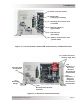
Figure 1-1, Power Switch, Status LED and Accessory Connection Ports .................................................3
Figure 1-2, Electrical Connection Points ...........................................................................................3
Figure 1-3, Left Side Features ........................................................................................................4
Figure 2-1, Simplifi ed Installation Diagram for Permanent Installations ................................................8
Figure 2-2, Approved Mounting Positions ....................................................................................... 10
Figure 2-3, MS Series Dimensions ................................................................................................. 11
Figure 2-4, DC and Battery Temperature Sensor Wiring ................................................................... 14
Figure 2-5, Battery Hardware Installation ......................................................................................16
Figure 2-6, Inverter DC Hardware Installation ................................................................................ 16
Figure 2-7, Battery Temperature Sensor ........................................................................................ 18
Figure 2-8, MS Series Inverter/Charger - AC Wiring ....................................................................... 21
Figure 2-9, MS Series Inverter/Charger - AC Wiring (Access Panel) .................................................. 21
Figure 2-10, AC Terminal Block ..................................................................................................... 22
Figure 2-11, AC Wiring for Single In - Single Out (30 A) Confi gurations ............................................. 25
Figure 2-12, AC Wiring for Single In - Single Out (60 A) Confi gurations ............................................. 26
Figure 2-13, AC Wiring for Single In - Dual Out Confi gurations ......................................................... 27
Figure 2-14, AC Wiring for Dual In - Single Out Confi gurations ......................................................... 28
Figure 2-15, AC Wiring for Dual In - Dual Out Confi gurations ............................................................ 29
Figure 2-16, Grounding System for MS Series ................................................................................ 30
Figure
2-17, Multiple Connections to DC Ground Rod (Method 1) ....................................................... 31
Figure 2-18, Multiple Connections to DC Ground Rod (Method 2) ....................................................... 32
Figure 2-19, Single Connection to DC Ground Rod (Method 3) .......................................................... 32
Figure 2-20, Neutral-to-Ground Connection (Inverter Mode) ............................................................. 35
Figure 2-21, Neutral-to-Ground Connection (Standby Mode) ............................................................. 35
Figure 2-22, Disconnecting the Ground-to-Neutral connection ........................................................... 36
Figure 2-23, Large ground wire connected to MS Series ................................................................... 36
Figure 2-24, Warning Label .......................................................................................................... 37
Figure 2-25, AC Voltage Checks .................................................................................................... 38
Figure 3-1, Power Flow - Inverter Mode .........................................................................................39
Figure 3-2, Power Flow - Standby Mode ......................................................................................... 40
Figure 3-3, Automatic 4-Stage Charging Graph ............................................................................... 41
Figure 3-4, BTS Temperature to Charge Voltage Change .................................................................. 42
Figure 3-5, Power Switch and Status Indicator ................................................................................ 44
Figure 4-1, Performing an Inverter Reset .......................................................................................48
Figure 4-2, MS Series Effi ciency Chart ........................................................................................... 50
Figure 4-3, MS Series Output Charger Current Chart ....................................................................... 50
Figure B-1, Series Battery Wiring .................................................................................................. 54
Figure B-2, Parallel Battery Wiring ................................................................................................ 54
Figure B-3, Series-Parallel Battery Wiring....................................................................................... 54
Figure B-4, Battery Bank Wiring Examples (12-volt) ........................................................................ 55
Figure B-5, Battery Bank Wiring Examples (24-volt) ........................................................................ 56
List of Tables
Table 1-1, Typical Appliance Power Consumption ...............................................................................6
Table 2-1, Recommended DC Wire/Overcurrent Device for Rated Use ................................................ 15
Table 2-2, DC Wire Size For Increased Distance .............................................................................. 16
Table 2-3, AC Input/Output Wiring Confi gurations ........................................................................... 24
Table 2-4, AC Grounding Electrode Conductor Sizing ....................................................................... 31
Table 2-5, Equipment Grounding Conductor Sizing .......................................................................... 33
Table 3-1, Inverter Battery Turn On/Off Levels ................................................................................ 43
Table 3-2, Inverter/Charger Default Values .................................................................................... 45
Table 4-1, Basic Troubleshooting ................................................................................................... 47