
Owner`s manual

© 2009 Magnum Energy IncPage 2
Introduction
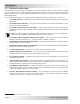
1.1 Features and Benefi ts
The MS Series inverter/charger is designed to allow easy access to wiring, circuit breakers, controls
and for viewing the LED (Light Emitting Diode) status indicator. Its die cast base plate with one
piece aluminum cover ensures maximum durability with minimum weight, as well as cooler more
effi cient operation.
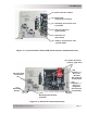
The front of the MS Series is equipped with the following features (see fi gures 1-1 and 1-2):
(1) Power Switch - a momentary push-button switch that alternately turns the inverter
ON or OFF.
(2) Status LED Indicator - this green LED illuminates to provide information on the
inverter or charger operation.
(3) Stack Connection Port (red label) - a RJ11 port that allows series-stacking and
accepts the optional RSAs (Remote Switch Adapters) which allows remote on/off switch
operation.
Info: The series-stacking capability, which allows two units to provide 120/240 VAC
output is only available on the MS4024 Series Inverter/Charger.
(4) Magnum Net Connection Port (green label) - a RJ11 port that accepts optional
Network capable accessories (i.e., Auto Gen Start or Battery Monitor).
(5) Remote Connection Port (blue label) - a RJ11 port that allows the optional remote
control display to be connected.
(6) BTS Connection Port (yellow label) - a RJ11 port that accepts the remote Battery
Temperature Sensor (BTS) accessory.
(7) Mounting Flange - used to secure the inverter to a shelf or wall.
(8) AC Entry/Exit Connections - two 3/4” knockouts provided with cable-clamp strain
reliefs to allow and hold the AC input and output fi eld wiring.
(9) Intake Air Vents - ventilation openings to pull in air to help keep the inverter cool
for peak performance.
(10) Positive DC Terminal - provides 360 degree connection point for the positive (+)
cable from the battery bank; provided with a 5/16-18 stainless Kep nut
1
on a 5/16-18 bolt
to hold the battery cable to the DC terminal which uses.
(11) Negative DC Terminal - provides 360 degree connection point for the negative (-)
cable from the battery bank; provided with a 5/16-18 stainless Kep nut
1
on a 5/16-18 bolt
to hold the battery cable to the DC terminal.
(12) DC Equipment Ground Terminal - this connection is used to tie the exposed
chassis of the inverter to the DC grounding system. This terminal accepts one CU/AL
conductor from #14 to # 2 AWG (21. to 33.6 mm
2
)
Note 1 - Hex nut with external tooth lock washer
•
•
•
•
•
•
•
•
•
•
•
•