
Owner`s manual

Page 3
© 2009 Magnum Energy Inc.
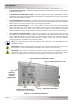
Introduction
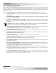
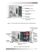
Figure 1-1, Power Switch, Status LED and Accessory Connection Ports
Figure 1-2, Electrical Connection Points
AC Entry/Exit
Connections
Mounting
Flange
(7)
(8)
Power ON/OFF Switch(1)
Status LED
(Charging/Inverting)
(2)
Stacking/Accessories Port
(red label)
(3)
Remote Port
(blue label)
(5)
Battery Temp Sensor Port
(yellow label)
(6)
Magnum Net Port
(green label)
(4)
Intake Air Vents
(and on right side)
(9)
DC Equipment Ground
Terminal
(12)
Positive (+)
DC Cover
(Positive
DC Terminal
underneath)
Negative (–)
DC Cover
(Negative
DC Terminal
underneath)
(11)
(10)