ME Series Modified Sine Wave Inverter/Chargers Owner’s Manual
Thank you from all of us at Sensata Technologies for purchasing this ME Series inverter/charger. The ME Series products include the ME2000, ME2012, ME2512 and ME3112 inverters; all under the Magnum-Dimensions brand from Sensata Technologies. We understand that you have many purchasing options in the marketplace, and we are pleased that you have decided on this product. This ME Series inverter/charger was proudly assembled and tested in the United States at our facility in Everett, Washington.
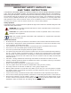
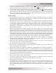
Safety Information IMPORTANT SAFETY INSTRUCTIONS SAVE THESE INSTRUCTIONS THIS MANUAL CONTAINS IMPORTANT INSTRUCTIONS FOR THE ME SERIES INVERTER/CHARGER THAT SHALL BE FOLLOWED DURING THE INSTALLATION AND OPERATION OF THIS PRODUCT. Before using the ME Series, read all instructions and cautionary markings. Also, be sure to review the individual manuals provided for each component of the system. The installation instructions are for use by qualified personnel only.
Safety Information • Overcurrent protection for the AC output wiring is not provided as an integral part of this inverter. Overcurrent protection of the AC output wiring must be provided as part of the system installation. Refer to Section 2.5 “AC Wiring” for more information. The AC output neutral conductor and the DC negative conductors are not connected (bonded) to the inverter chassis. Both the input and output conductors are isolated from the enclosure and each other.
Safety Information CONSIGNES DE SÉCURITÉ IMPORTANTES CONSERVER CES INSTRUCTIONS CE MANUEL CONTIENT DE IMPORTANTES POUR LA SÉRIE ME ONDULEUR/CHARGEUR QUI DOIVENT ETRE SUIVIES PENDANT L’INSTALLATION ET FONCTIONNEMENT DE CE PRODUIT. Avant d’utiliser la série ME, lire toutes les instructions etles mises en garde. Aussi, n’oubliez pas depasser en revue les différents manuels fournispour chaque composant du système. Lesinstructions d’installation sont pour une utilisationpar du personnel qualifié.
Safety Information • • La protection contre les surintensités pour le câblage de sortie CA n’est pas fourni en tant que partie intégrante de cet inverseur. Protection contre les surintensités du câblage de sortie CA doit être fournie dans le cadre de l’installation du système. Reportez-vous à la Section 2.5 Câblage ca pour plus d’informations. Le conducteur de courant alternatif de sortie neutre et les conducteurs à courant continu négatives ne sont pas connectés (servitude) au châssis inverseur.
Table of Contents 1.0 1.1 1.2 1.3 2.0 2.1 2.2 2.3 2.4 2.5 2.6 2.7 2.8 2.9 3.0 3.1 3.2 3.3 3.4 3.5 3.6 3.7 3.8 3.9 3.10 4.0 4.1 4.2 4.3 4.4 Introduction ........................................................................................... 1 How an Inverter/Charger Works ............................................................................ 1 What Appliances will run from a Modified Sine Wave Inverter..................................... 2 Features and Benefits.................................
List of Figures Figure Figure Figure Figure Figure Figure Figure Figure Figure Figure Figure Figure Figure Figure Figure Figure Figure Figure Figure Figure Figure Figure Figure Figure Figure Figure Figure Figure Figure Figure Figure Figure Figure Figure Figure Figure Figure 1-1, Power Switch, Status LED, and Accessory Connection Ports ................................ 2 1-2, Electrical Connection Points ........................................................................... 3 1-3, Left Side Features ...
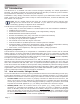
Introduction 1.0 Introduction The ME Series is a modified sine wave inverter designed especially for mobile applications. Powerful, yet simple to operate, this inverter/charger will provide you with the years of troublefree performance—backed by our limited 3-year warranty. Installation is easy. Simply connect the inverter’s output to your distribution circuits or electrical panel, connect your AC to the inverter’s easy-to-reach terminal block, connect the batteries, and then switch it on for power.
Introduction 1.2 What Appliances will run from a Modified Sine Wave Inverter Today’s inverters come in two basic output waveforms: modified sine wave (a modified square wave—see Figure 1-5) and pure sine wave. Modified sine wave inverters approximate a pure sine waveform and will run most appliances and electronics without any problems. These inverters are less expensive, and therefore, offer a viable alternative to more expensive pure sine inverters.
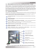
Introduction 7 DC Equipment Ground Terminal – this connection is used to tie the exposed chassis of the inverter to the DC grounding system. This terminal accepts CU/AL conductors from #14 to #2 AWG (2.1 to 33.6 mm2). 8 AC Input/Output Connections – two 3/4” knockouts provided with cable-clamp strain reliefs to allow and hold the AC input and output field wiring. 9 Intake Air Vents – ventilation openings to pull in air to help keep the inverter cool for peak performance.
Introduction The left side of the ME Series is equipped with the following features (see Figures 1-3 and 1-4): 13 Exhaust Air Vents – ventilation openings that allow heated air to be removed by the internal cooling fan. 14 Model/Serial Number Label – includes model/serial number information, date of manufacture, and inverter and charger specifications. See the ME specifications in Appendix A for more information and the different models that are available.
Installation 2.0 Installation WARNING: Installations should be performed by qualified personnel, such as a licensed or certified electrician. It is the installer’s responsibility to determine which safety codes apply and to ensure that all applicable installation requirements are followed. Applicable installation codes vary depending on the specific location and application of the installation. CAUTION: Review the “Important Product Safety Information” on pages ii-v before any installation.
Installation Shore Power 120/240 VAC Output Generator Power 120/240 VAC Output ME-AGS-N Auto Gen Start Controller (Magnum Accessory) tor or Genera Flux Capacit ME-RC50 AC Transfer Switch ME-ARC50 PWR FAULT CHG SELECT INV ON/OFF CHARGER ON/ OFF INVERTE R SHORE AGS METER SETUP TECH Remote Controls (Magnum Accessories) Main Panel OFF OFF OFF OFF ON ON ON OFF ON OFF OFF ON ON OFF OFF ON ON ON OFF ON ON OFF ON ON OFF ON ON ON OFF OFF ON OFF ON ON ON OFF OFF ON O
Installation 2.1.3 Locating the Inverter Only install the inverter in a location that meets the following requirements: Clean and Dry – The inverter should not be installed in an area that allows dust, fumes, insects, or rodents to enter or block the inverter’s ventilation openings. This area also must be free from any risk of condensation, water, or any other liquid that can enter or fall on the inverter.
Installation 2.2 Mounting the Inverter The inverter base can reach a temperature up to 90°C (194°F) and should be mounted on a noncombustible surface*. This surface and the mounting hardware must also be capable of supporting at least twice the weight of the inverter.
Left Side 20 Page 9 20 13 ¾" (34.9 cm) Mounting Holes (x4) Keyhole slots (x4) Use up to 9/32" (7 mm) screw/bolt Mounting Holes 8" (20.3 cm) Bottom 12" (30.5 cm) Front 12 ⅝" (32.1 cm) Top Air Intake Vents Air Intake Vents 4 ⅞" (12.4 cm) 2" (5.1 cm) 4 ⅞" (12.4 cm) 6 ⅝" (16.
Left Side © 2015 Sensata Technologies 20 13 ¾" (34.9 cm) Mounting Holes (x4) Use up to 9/32" (7 mm) screw/bolt Keyhole slots (x4) Mounting Holes 6 ⅝" (16.8 cm) Bottom 12" (30.5 cm) Front 12 ⅝" (32.1 cm) Top Air Intake Vents Air Intake Vents 4 ⅞" (12.4 cm) 2" (5.1 cm) 4 ⅞" (12.4 cm) 6 ⅝" (16.
Installation 2.3 Wiring the Inverter – General Requirements This section describes the requirements and recommendations for wiring the ME Series inverter/ charger. Before wiring the inverter/charger, read all instructions. All wiring should meet all local codes and industry standards, and be performed by qualified personnel such as a licensed electrician. The NEC (National Electric Code, ANSI/NFPA 70) for the United States and the CEC (Canadian Electrical Code) for Canada provide safe wiring standards.
Installation 2.4 DC Wiring This section describes the inverter’s required DC wire sizes, the recommended disconnect/ overcurrent protection, and how to make the DC connections to the inverter and the battery bank. Refer to Figure 2-5 when connecting the DC wires. WARNING: Even though DC voltage is “low voltage”, significant hazards may be present, particularly from short circuits of the battery system.
Installation ME Series Inverter/Charger front view BTS BTS Inverter’s DC Negative Connection Inverter’s DC Positive Connection Inverter’s Equipment Ground Wire Battery Temp Sensor Cable Battery Disconnect Switch Battery Bank’s Equipment Ground Wire ON DC Shunt Battery Bank’s Negative Cable OFF Battery Bank’s Positive Cable Fuse 12-volt Battery Bank Figure 2-5, DC and Battery Temperature Sensor Wiring Page 13 © 2015 Sensata Technologies
Installation 2.4.1 DC Wire Sizing It is important to use the correct DC wire to achieve maximum efficiency from the system and reduce fire hazards associated with overheating. Always keep your wire runs as short as practical to help prevent low voltage shutdowns and keep the DC breaker from nuisance tripping (or open fuses) because of increased current draw. See Table 2-1 to select the required minimum DC wire size (and corresponding overcurrent device) based on your inverter model.
Installation Table 2-2, DC Wire Size For Increased Distance (in free air) Minimum Recommended DC Wire Size (one way)* 5 feet or less 5 to 10 feet 10 to 15 feet ME2000 #2/0 AWG (67.4 mm2) #4/0 AWG (107.16 mm2) #4/0 AWG (107.16 mm2) x2 ME2012 #2/0 AWG (67.4 mm2) #4/0 AWG (107.16 mm2) #4/0 AWG (107.16 mm2) x2 ME2512 #4/0 AWG (107.16 mm2) #4/0 AWG (107.16 mm2) x2 not recommended ME3112 #4/0 AWG (107.16 mm2) #4/0 AWG (107.
Installation 2.4.4 Wiring the Battery Bank WARNING: Lethal currents will be present if the positive and negative cables attached to the battery bank touch each other. During the installation and wiring process, ensure the cable ends are insulated or covered to prevent touching/shorting the cables.
Installation 2.4.6 Wiring the Inverter to the Battery Bank CAUTION: The inverter is NOT reverse polarity protected—if this happens, the inverter will be damaged and will not be covered under warranty. Before connecting the DC wires from the batteries to the inverter, verify the correct battery voltage and polarity using a voltmeter. If the positive terminal of the battery is connected to the negative terminal of the inverter and vice versa, severe damage will result.
Installation 2.5 AC Wiring This section provides information on how to make the AC connections to the ME inverter using the correct AC wire size and the corresponding overcurrent protection. Refer to Figures 2-10 through 2-16 for visual overviews of the various AC wiring configurations. 2.5.
Installation 2.5.3 Recommended GFCIs (Ground Fault Circuit Interrupters) Some electrical safety codes require the use of GFCI’s.
Installation 2.5.5 AC Conductor Wiring (ME2012, ME2512, and ME3112 models) The following steps are basic guidelines for installing and connecting the AC wiring to and from all ME Series inverters (except ME2000 Series model inverters—for instructions on wiring ME2000 Series model inverters, refer to Section 2.5.7). Before proceeding, refer to Table 2-3 to determine your AC wiring configurations.
Installation 2.5.6 AC Wiring Configuration (ME2012, ME2512, and ME3112 models) Table 2-3 provides the different wiring configurations for installing and connecting the AC conductors into and out of the ME2012, ME2512, and ME3112 model inverters (see Figures 2-9 to 2-13 for installation diagrams). Refer to Table 2-4 (and Figures 2-14 & 2-15) for the ME2000 models.
Installation AC Terminal Block (AC input and output wiring) SINGLE IN / SINGLE OUT (30A) wiring ME Series Inverter AC NEUT IN (from Main Panel) AC HOT 1 IN (from Main Panel) AC HOT 1 OUT (to Sub-Panel) AC NEUT OUT (to Sub-Panel) AC GROUNDS (to/from both panels) In mobile installations: neutral is typically not connected to ground in the main panel.
Installation AC Terminal Block (AC input and output wiring) SINGLE IN / SINGLE OUT (60A) wiring ME Series Inverter AC NEUT IN (from Main Panel) AC HOT 1 IN (from Main Panel) AC HOT 2 IN (from Main Panel) AC HOT 1 OUT (to Sub-Panel) AC HOT 2 OUT (to Sub-Panel) AC NEUT OUT (to Sub-Panel) AC GROUNDS (to/from both panels) In mobile installations: neutral is typically not connected to ground in the main panel.
Installation AC Terminal Block (AC input and output wiring) SINGLE IN / DUAL OUT wiring Has optional 15-amp or 20amp branch-rated circuit breakers (on side of unit). ME2012-15B or ME2012-20B Inverter AC NEUT IN (from Main Panel) AC HOT 1 IN (from Main Panel) AC HOT 2 IN (from Main Panel) AC HOT 1 OUT AC HOT 2 OUT AC NEUT OUT (x2) AC GROUNDS (to/from both panels) In mobile installations: neutral is typically not connected to ground in the main panel.
Installation AC Terminal Block (AC input and output wiring) DUAL IN / SINGLE OUT wiring ME Series Inverter AC NEUT IN (from Main Panel) AC HOT 1 IN (from Main Panel) AC HOT 2 IN (from Main Panel) AC HOT 2 OUT (to Sub-Panel) AC NEUT OUT (to Sub-Panel) AC GROUNDS (to/from both panels) In mobile installations: neutral is typically not connected to ground in the main panel.
Installation AC Terminal Block (AC input and output wiring) DUAL IN / DUAL OUT wiring ME Series Inverter AC NEUT IN (from Main Panel) AC HOT 1 IN (from Main Panel) AC HOT 2 IN (from Main Panel) AC HOT 1 OUT (to Sub-Panel) AC HOT 2 OUT (to Sub-Panel) AC NEUT OUT (to Sub-Panel) AC GROUNDS (to/from both panels) In mobile installations: neutral is typically not connected to ground in the main panel.
Installation 2.5.7 AC Conductor Wiring (ME2000 models) The ME2000 offers a cost-effective alternative to the ME2012 while still providing the same features. This model has a slightly smaller height, but otherwise has the same footprint as the other ME Series inverters. The ME2000 uses wire leads to connect the AC wires and can be wired in a single in-single out configuration, as well as a single in-dual out configuration (-15B & -20B).
Installation 2.5.8 AC Wiring Configuration (ME2000 models) The following table provides the different wiring configurations for installing and connecting the AC conductors into and out of ME2000 model inverters (see Figures 2-15 and 2-16 for installation diagrams showing these configurations).
Installation AC Wiring Compartment (AC input and output wiring) SINGLE IN / SINGLE OUT (30A) wiring ME2000 Series Inverter BLACK AC HOT IN WHITE AC NEUT IN GREEN AC GROUND AC GROUND WHITE w/ BLACK AC NEUT OUT BLUE AC HOT 1 OUT In mobile installations: neutral is typically not connected to ground in the main panel.
Installation AC Wiring Compartment (AC input and output wiring) SINGLE IN / DUAL OUT wiring BLACK Has optional 15-amp or 20amp branch-rated circuit breakers (on side of unit). AC HOT IN WHITE ME2000-15B/-20B Inverters AC NEUT IN GREEN AC GROUND AC GROUND (x2) WHITE w/ BLACK AC NEUT OUT WHITE w/ BLACK AC NEUT OUT BLUE AC HOT 1 OUT ORANGE AC HOT 2 OUT In mobile installations: neutral is typically not connected to ground in the main panel.
Installation 2.6 Grounding Inverters The inverter/charger should always be connected to a permanent, grounded wiring system. An inverter system that is properly grounded will limit the risk of electrical shock, reduce radio frequency noise from the inverter, and minimize excessive surge voltages induced by lightning. This is done by ensuring there is a well-defined, very low-resistance path from the electrical system to the grounding system.
Installation 2.6.2 Grounding on Boats When installing the ME Series inverter/charger on a boat, there are several considerations that must be followed when grounding to ensure a safe installation, prevent galvanic corrosion, and adhere to American Boat and Yacht Council (ABYC) standards. Ensure a Safe Ground Connection When AC on the boat is being supplied by shorepower (also referred to as “utility power”), the onboard neutral should be connected to safety ground on the dock.
Installation 2.6.3 Neutral to Safety Ground Bonding The recommended standards for safely wiring mobile and marine installations require that the neutral and safety ground be connected at the AC source; whether it is an inverter, utility power, or a generator. This is to establish a specification that maximizes the possibility that a circuit breaker will activate if a hot-wire-to-ground fault occurs.
Installation 2.6.4 Connecting a Large DC Ground Wire Marine installations require the DC ground wire to be the same size or one size smaller than the negative cable. Use the following steps to allow a larger ground wire to be connected. WARNING: Fire and Shock Hazard – disconnect all AC and DC sources before working in the AC wiring compartment. 1. Remove the inverter’s AC access cover plate (see Figure 1-3, Item 15). 2. Locate the DC Equipment Ground Terminal (see Figure 1-2, Item 7). 3.
Installation 2.8 Final Inspection 1. Verify all cable runs are secured with wire ties or other non-conductive fasteners to prevent chafing, or damage from movement and vibration. 2. Verify strain reliefs or grommets are in place to prevent damage to the wiring where it passes through walls, bulkheads, or other openings. 3. Verify all AC connections are correct and torqued to a maximum of 16 lbf-in (1.8 N-m). 4. Replace the covers on the main electrical/distribution panel. 5.
Installation AC Terminal Block AC Output 120 Vac (± 5%) 3 0 30 Neutral to Ground < 0.5 Vac Figure 2-21, AC Voltage Checks (Models with terminal block) AC Wiring Compartment BLACK WHITE GREEN Neutral to Ground < 0.5 Vac 3 0 WHITE W/BLACK AC Output 120 Vac (± 5%) BLUE Figure 2-22, AC Voltage Checks (ME2000 model) AC Wiring Compartment BLACK WHITE Neutral to Ground < 0.5 Vac GREEN AC Output 120 Vac (± 5%) .WHITE w./ BLACK 2 0 AC Output 120 Vac (± 5%) 2 0 3 0 .WHITE w.
Operation 3.0 Operation The ME Series inverter has two normal operating routines: Inverter mode, which powers your loads using the batteries; and Standby mode, which transfers the incoming AC power (e.g., utility power or a generator) to power your loads and to recharge the batteries. This inverter also includes an extensive protection circuitry to shut down the inverter under certain fault conditions. 3.1 Inverter Mode When the ME Series is first powered up, it defaults to the OFF mode.
Operation 3.2 Standby Mode The ME Series features an automatic transfer relay and an internal battery charger when operating in Standby mode. Standby mode begins whenever AC power (utility or generator) is connected to the inverter’s AC input. Once the AC voltage and frequency of the incoming AC power is within the AC input limits, an automatic AC transfer relay is activated. This transfer relay passes the incoming AC power through the inverter to power the AC loads on the inverter’s output.
Operation The Charge mode provides up to four separate charging stages: Bulk Charging, Absorb Charging, Float Charging, and Full Charge (see Figure 3-3). Bulk Charging: This is the initial stage of charging. While bulk charging, the charger supplies the battery with constant current. The charger will remain in bulk charge until the absorption charge voltage (determined by the Battery Type selection*) is achieved. The inverter’s green LED stays ON (solid) to indicate bulk charging.
Operation 3.4 Transfer Time While in Standby mode, the AC input is continually monitored. Whenever AC power falls below the VAC dropout voltage (80 VAC, default setting), the inverter automatically transfers back to Inverter mode with minimum interruption to your appliances—as long as the inverter is turned on. The transfer from Standby mode to Inverter mode occurs in approximately 16 milliseconds.
Operation 3.6 Protection Circuitry Operation The inverter is protected against fault conditions, and in normal usage it will be rare to see any. However, if a condition occurs that is outside the inverter’s normal operating parameters, it will shut down and attempt to protect itself, the battery bank, and your AC loads. If there is a condition that causes the inverter to shut down, it may be one of the following conditions [also refer to the Troubleshooting section (Section 4.
Operation 3.7 Inverter Startup Power ON/OFF Switch – The inverter can be turned on/off by lightly pressing and releasing the Power ON/OFF switch on the front (see Figure 3-5). When the inverter is first connected to the batteries, or when its automatic protection circuit has turned the inverter off, the ON/OFF switch will need to be pressed to start the unit (or reset per Section 4.4). Once the inverter has been turned on, pressing the Power ON/OFF switch alternately turns the inverter on and off.
Operation 3.8 Factory Default Values The ME Series inverter/charger uses default values for the adjustable settings (Table 3-2) that are adequate for most installations. If operating parameters need to be changed from the default values, an optional remote control/display can be used to make those changes. To help you determine if you need the a remote display, information on the inverter/charger settings that can be changed is provided below.
Operation 3.9 Inverter Fan Operation The inverter contains two internal cooling fans that are automatically controlled. The speed of these fans is determined either by the internal temperature of the inverter or by the load on the inverter. The inverter’s fans will come on under the conditions listed below: • Fans run full speed if the internal transistors (FETS) or the power transformer reaches 80°C degrees Celsius (176°F), or the inverter is running at 100% of its rated load.
Maintenance and Troubleshooting 4.0 Maintenance and Troubleshooting The following information is provided to help you keep your ME Series inverter/charger in optimum operational condition. 4.1 Recommended Inverter and Battery Care The ME Series inverter/charger is designed to provide you with years of trouble-free service.
Maintenance and Troubleshooting Symptom Possible Cause Recommended Solution No output power. Inverter LED is OFF. (Cont.) Battery voltage is too high. The inverter automatically resets and resumes operation when the battery voltage drops to the HBCI voltage or lower. Condition usually only occurs when an additional charging source (external charging sources) is used to charge the battery bank. Reduce/turn off any other charger to the inverter batteries to allow voltage level to drop.
Maintenance and Troubleshooting 4.4 Resetting the Inverter Under some fault conditions (e.g., an internal fault), the inverter will need to be reset. Prior to performing any reset, ensure all AC power (utility, generator, shorepower) is removed from the inverter’s input. CAUTION: If AC is connected while performing an inverter reset, damage may occur. 4.4.1 Performing an Inverter Reset To perform an inverter reset (also known as a “soft reset”): 1.
Appendix A – Specifications and Optional Equipment Appendix A – Specifications and Optional Equipment A-1 Inverter/Charger Specifications Models ME2000 (-15B, -20B) ME2012 (-15B, -20B) ME2512 ME3112 Input Battery Voltage Range 9 to 16 VDC 9 to 16 VDC 9 to 16 VDC 9 to 16 VDC Absolute Maximum DC Input 25 VDC 25 VDC 25 VDC 25 VDC Inverter Specifications AC Output Voltage Accuracy 120 VAC ±5% (≤ continuous power) Output Frequency and Accuracy 60 Hz ± 0.
Appendix A – Specifications and Optional Equipment A-2 Optional Equipment and Accessories The following Sensata Technologies components are available for use with the ME Series inverter/ charger. Some of these items are required depending upon the intended use of the inverter. Smart Battery Combiner The Smart Battery Combiner (ME-SBCTM) is designed to monitor and charge a second battery using a portion of the current that is charging the main battery.
Appendix B – Battery Information Appendix B – Battery Information B-1 Battery Location Periodic maintenance (e.g., checking connections, cleaning, watering) on batteries is required. Locate the batteries in an accessible location to perform this maintenance. Batteries must be mounted in a clean, dry, ventilated environment where they are protected from high and low temperatures. The battery bank should be located as close to the inverter as possible without limiting access to the inverter’s disconnects.
Appendix B – Battery Information B-5 Battery Bank Sizing Worksheet Complete the steps below to determine the battery bank size required to power your AC loads: 1.
Appendix B – Battery Information B-6 Battery Wiring Configurations The battery bank must be wired to match the inverter’s DC input voltage. In addition, the batteries can be wired to provide additional run time. The various wiring configurations include: B-6.1 Series Wiring Wiring batteries in series increases the battery bank’s output voltage. A series connection combines each battery in a string until the total voltage matches the inverter’s DC requirement.
Appendix B – Battery Information overcurrent protection String (12 VDC @ 100 AH) to 12 VDC inverter (total capacity = 100 AH) 12 VDC battery (100 AH) 12-volt battery bank (one string of one 12-volt battery) overcurrent protection Series String (6 VDC + 6 VDC) 6 VDC battery (200 AH) to 12 VDC inverter (total capacity = 200 AH) 6 VDC battery (200 AH) 12-volt battery bank (one string of two 6-volt batteries wired in series) overcurrent protection Parallel String (100 AH + 100 AH) 12 VDC battery (100
Appendix C – Power Consumption & Output Waveforms Appendix C – Power Consumption & Output Waveforms C-1 Appliances and Run Time The ME Series inverter/charger powers a wide range of household appliances including small motors, hair dryers, clocks, and other electrical devices. As with any appliance using batteries for power, there is a certain length of time that it can run—i.e., “run time.
Appendix D – Inverter/Charger Terminology Appendix D – Inverter/Charger Terminology The following is a glossary of terms with which you may not be familiar. They appear in the various descriptions of inverter and battery charger operation. Absorbtion Stage – In this second stage of three stage charging, the batteries are held at a constant voltage (the absorb voltage setting) and the battery is charged to its maximum capacity. AC (Alternating Current) – Electrical current that varies with time (i.e.
Appendix D – Inverter/Charger Terminology Locked Rotor Amps – The current drawn by an electric motor with the shaft or rotor stopped and locked in position. This can be used to determine if an inverter has enough surge current to start a motor. If the inverter is capable of producing more amperage than the locked rotor amps rating of a motor, it will most likely start the motor easily. NEC (National Electric Code) – The guidelines and acceptable practices for electrical installations in the USA.
Appendix E – Warranty & Service Appendix E – Warranty & Service E-1 Limited Warranty Sensata Technologies warrants this ME Series inverter/charger to be free from defects in material and workmanship that result in product failure during normal usage, according to the following terms and conditions: 1. The limited warranty for the product extends for 36 months beginning from the product’s original date of purchase. 2.
Magnum-Dimensions Products Manufactured by: Sensata Technologies 2211 West Casino Rd. Everett, WA 98204 Phone: 425-353-8833 Fax: 425-353-8390 Web: www.Magnum-Dimensions.