
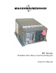
Installation Manual

© 2015 Sensata TechnologiesPage ii
Safety Information
IMPORTANT SAFETY INSTRUCTIONS
SAVE THESE INSTRUCTIONS
THIS MANUAL CONTAINS IMPORTANT INSTRUCTIONS FOR THE ME SERIES INVERTER/CHARGER
THAT SHALL BE FOLLOWED DURING THE INSTALLATION AND OPERATION OF THIS PRODUCT.
Before using the ME Series, read all instructions and cautionary markings. Also, be sure to review
the individual manuals provided for each component of the system. The installation instructions
are for use by qualified personnel only. Do not perform any installation or servicing other than
that specified in this owner’s manual unless you are qualified to do so. Incorrect installation or
servicing may result in a risk of electric shock, fire, or other safety hazard.
Safety Symbols
The following safety symbols have been placed throughout this manual to indicate dangerous and
important safety instructions.
WARNING: This symbol indicates that failure to take a specifi ed action could result in
physical harm to the user.
CAUTION: This symbol indicates that failure to take a specifi ed action could result in
damage to the equipment.
Info: This symbol indicates information that emphasizes or supplements important
points of the main text.
Safety Precautions
• All electrical work must be performed in accordance with local and national electrical codes.
• This product is designed for indoor/compartment installation. It must not be exposed to rain,
snow, moisture, or liquids of any type.
• Use insulated tools to reduce the chance of electrical shock or accidental short circuits.
• There are no user-serviceable parts contained in this product.
• This unit is provided with integral protection against overloads.
• Live power may be present at more than one point since an inverter utilizes both DC (batteries,
PV, etc.,) and AC (utility or generator) power. To reduce risk of electric shock, ensure all DC
and AC wiring is disconnected prior to installing or performing maintenance on the inverter.
Turning off the inverter will not reduce this risk, the inverter must be totally disconnected
from all sources.
• Use Class 1 wiring methods for field wiring connections to terminals of a Class 2 circuit.
• Listed or labeled equipment shall be installed and used in accordance with any instructions
included in the listing or labeling.
• Always verify proper wiring prior to starting the inverter.
• Use only copper wires with a minimum temperature rating of 90°C (194°F).
• AC wiring must be no less than 10 AWG (5.3 mm²) gauge copper wire.
• Battery cables should be no less than #4/0 AWG (107.2 mm²) for 12-volt systems. Crimped
and sealed copper ring terminal lugs with a 5/16 hole should be used to connect to the DC
terminals on the inverter.
• Torque all AC wiring connections and DC cable connections to the required torque values.
• The inverter must be properly installed, see Section 2.2 “Mounting the Inverter” in this manual.
• Overcurrent protection for the battery supply is not provided as an integral part of this
inverter. Overcurrent protection of the battery cables must be provided as part of the system
installation. Refer to Section 2.4 “DC Wiring” for more information.