MM-AE Series Inverter/Chargers Owner’s Manual
Disclaimer of Liability The use of this manual and the conditions or methods of installation, operation, use, and maintenance of the MM-AE Series Inverter/ Charger are beyond the control of Magnum Energy, Inc. Therefore, this company assumes no responsibility and expressly disclaims any liability for loss, damage, or expense whether direct, indirect, consequential, or incidental that may arise out of or be in any way connected with such installation, operation, use, or maintenance.
Safety symbols To reduce the risk of electrical shock, fire, or other safety hazard, the following safety symbols have been placed throughout this manual to indicate dangerous and important safety instructions. WARNING: This symbol indicates that failure to take a specified action could result in physical harm to the user. CAUTION: This symbol indicates that failure to take a specified action could result in damage to the equipment.
• No overcurrent protection for the battery supply is provided as an integral part of this inverter. Overcurrent protection of the battery cables must be provided as part of the installation. • No overcurrent protection for the AC output wiring is provided as an integral part of this inverter. Overcurrent protection of the AC output wiring must be provided as part of the installation. IMPORTANT BATTERY SAFETY INSTRUCTIONS • Wear eye protection (safety glasses) when working with batteries.
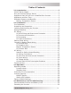
Table of Contents 1.0 Introduction ..................................................................1 MM-AE Series Models ............................................................ 1 How an Inverter/Charger Works ............................................. 2 Appliances that will run from a Modified Sine Inverter ............... 2 Appliances and Run Time....................................................... 2 Standard Features and Benefits ..............................................
Table of Contents 5.0 Specifications ..............................................................34 Appendix A - Optional Equipment and Accessories ............35 Appendix B - Battery Information .....................................36 Battery Bank Sizing .............................................................36 Battery Types .....................................................................36 Battery Configuration ...........................................................36 Series Wiring ......
1.0 Introduction 1.0 Introduction Congratulations on your purchase of an MM-AE Series inverter/charger from Magnum Energy, Inc. This product is designed especially for your back-up power or standalone application. Powerful, yet simple to use, the Magnum Energy inverter will provide you with years of trouble-free use. Please read this chapter to familiarize yourself with the features and benefits of your particular MM-AE Series model.
1.0 Introduction How an Inverter/Charger Works An inverter takes direct current (DC) from your batteries and turns it into alternating current (AC), like you use at home. With MM-AE Series models, it also takes alternating current (when connected to a generator or to utility power) and transforms it into direct current to recharge your batteries.
1.0 Introduction Standard Features and Benefits The MM-AE Series inverter/charger converts 12 or 24 volts (depending on model) direct current (VDC) power from your battery to 120 volts alternating current (VAC) power. The multi-stage battery charger optimizes incoming AC power using Power Factor Correction (PFC) technology to keep the inverter’s battery bank fully charged.
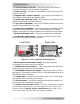
1.0 Introduction 1. Inverter Status Indicator - this green LED illuminates to provide information on the inverter’s operation. 2. Power Switch - momentary pushbutton switch that turns the inverter on or off. 3. Negative DC Terminal (black) - the inverter’s connection to the negative terminal on the battery bank. 4. Positive DC Terminal (red) - the inverter’s connection to the positive terminal on the battery bank. 5.
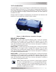
1.0 Introduction 15 16 17 Figure 4, Left Side Features 15. AC Output Connection - AC knockout (output) for hardwiring. 16. AC Input Connection - AC knockout (input) for hardwiring. 17. DC Ground Terminal - this connection is used to tie the exposed chassis of the inverter to the DC grounding system. This terminal accepts CU/AL conductors from #14 AWG to #6 AWG. Battery Temperature Sensor A plug-in external Battery Temperature Sensor (BTS) is provided for units with the battery charger feature.
2.0 Installation 2.0 Installation Pre-Installation Before installing the inverter, read the entire Installation section. The more thorough you plan in the beginning, the better your inverter needs will be met. WARNING: Installations should be performed by qualified personnel, such as a licensed or certified electrician. It is the installer’s responsibility to determine which safety codes apply, and to ensure that all applicable installation requirements are followed.
2.0 Installation M M -A E S e rie s In ve rte r A C IN DC Ground DC d isco n n e ct and o ve rcu rre n t d e vice AC OU T AC M a in P a n e l B attery B ank AC S u b -P a n e l TV AC O utlet T ools VC R A C Loads Figure 6, Basic Installation Diagram © 2010 Magnum Energy, Inc.
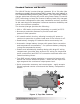
2.0 Installation Locating and Mounting the Inverter WARNINGS: • Do not mount the inverter near any flammable or combustible fluid or components. • Provide adequate clearance/ventilation to the inverter. • Mount only on a non-combustible surface. • Maximum ambient temperature around the inverter must not exceed 77° F (25° C) to meet power specifications.
2.0 Installation Safe - Keep any flammable/combustible material (e.g., paper, cloth, plastic, etc.) that may be ignited by heat, sparks, or flames at a minimum distance of 2 feet (60 cm) away from the inverter. Do not install this inverter in any area that contains extremely flammable liquids like gasoline or propane, or in locations that require ignitionprotected devices. Close to the battery bank - As with any inverter, it should be located as close to the batteries as possible.
2.0 Installation M ounting holes x 4 [¼ ” ( 0.25 ") diam eter ] ~ 4 11 /16 " ( 4.66 ") 10 .0" ~ 16 5/8 " (16 .59 ") ~6 3/4 " (6.71") ~ 7 ½ " (7.51") ~ 8 7 /16 " (8.41 ") Figure 8, MM-AE Series Inverter/Charger Dimensions Wiring Guidelines • Before connecting any wires, determine all wire routes to and from the inverter throughout the home or cabin.
2.0 Installation • DC wires and cables should be tied together with wire ties or electrical tape approximately every 6 inches. This helps improve the surge capability and reduces the effects of inductance, which improves the inverter waveform and reduces wear on the inverter’s filter capacitors. • Use only copper wires with a minimum temperature rating of 75°C.
2.0 Installation The DC wires must have soldered and crimped lugs, crimped copper compression lugs, or aluminum mechanical lugs. Soldered connections alone are not acceptable for this application.
2.
2.0 Installation DC Cable Connections When connecting the DC cable to the battery or to the inverter’s DC terminals, the hardware should be installed in the correct order to prevent high resistance connections from heating up and possibly causing the connections to melt. Follow Figures 9 and 10 to stack the hardware correctly. Tighten the terminal connections from 10 to 12 foot-pounds. CAUTION: Do not put anything between the DC cable ring lug and the battery terminal post or inverter’s DC terminal.
2.0 Installation Battery Bank Wiring WARNING: Lethal currents will be present if the positive and negative cables attached to the battery bank touch each other. During the installation and wiring process, ensure the cable ends are insulated or covered to prevent touching/shorting the cables.
2.0 Installation CAUTION: The inverter is NOT reverse polarity protected. If this happens, the inverter will be damaged and will not be covered under warranty. Before connecting the DC wires from the batteries to the inverter, verify the correct battery voltage and polarity using a voltmeter. If the positive terminal of the battery is connected to the negative terminal of the inverter and vice versa, severe damage will result.
2.0 Installation Connect a short wire (same rating as the DC wires) to one end of the fuse block and the other end of the short wire to the positive terminal of the last battery string (see Figure 16). This is essential to ensure even charging and discharging across the entire battery bank.
2.0 Installation AC Wiring Connections For all hardwired inverter models, the AC input and output wiring is performed in the AC wiring compartment. This compartment is located on the top panel (see Figure 2, Item 8). If installed, remove the two Phillips screws on the cover to access the AC wiring compartment and locate the inverter’s AC wiring. There is a label located in the AC access compartment which gives information on which wires are used for the AC input and output.
2.0 Installation Overcurrent protection must be provided by fuses or circuit-breakers, and must be properly sized and rated for the wire they are protecting and the appliances being powered. An external disconnect device is required for both the AC input and AC output wiring. Most inverter’s that are “hardwired” use a service/ distribution panel wired to the inverter’s input (main panel), and a dedicated panel between the inverter’s output wiring and the AC loads (sub-panel).
2.0 Installation N e u tra l In (w h ite) AC G ro u n d In /O u t (g re e n) N e u tra l O u t (w h ite w/ b la ck strip e ) H ot In H ot Out (re d) (b la ck) Strain reliefs AC IN AC O UT Figure 11, AC Wiring Connections AC Output Wiring CAUTION: The inverter’s AC output must never be connected to an AC power source. This will cause severe damage to the inverter and is not covered under warranty.
2.0 Installation 4. Remove about two inches of the insulating jacket from the AC cable, and then separate the three wires and strip about 3/4” of insulation from each wire. 5. Using approved AC wire connectors, connect the outgoing Hot Out, Neutral Out, and AC Ground wires to the MM-AE Series’ AC wires colored red (HOT OUT), white with black stripe (NEU OUT), and green (AC GROUND) respectively. Gently pull on the wires to ensure they are securely held together, and check to see that no bare wire is exposed.
2.0 Installation 3. Prior to turning on the inverter, make sure all connected loads (e.g., appliances) are switched OFF or disconnected from the AC outlets. 4. a. If a remote switch is connected, press the ON/OFF switch to turn the inverter on. b. If there is not a remote switch connected, lightly press and release the inverter’s ON/OFF power switch — located on the top of the inverter — to turn the inverter on.
3.0 Operation 3.0 Operation Operating Modes The MM-AE Series inverter/charger has two normal operating routines; Inverter Mode, which powers your loads using the batteries, and Standby Mode, which transfers the incoming AC power (i.e., utility power or a generator) to power your loads and also uses this incoming power to recharge the batteries. This inverter also includes an extensive protection circuitry that shuts down the inverter under certain fault conditions.
3.0 Operation Standby Mode The MM-AE Series features an automatic transfer relay and an internal battery charger when operating in the Standby Mode. The Standby Mode begins whenever AC power (utility or generator) is connected to the inverter’s AC input. Once the AC voltage and frequency of the incoming AC power is within the AC input limits, an automatic AC transfer relay is activated. This transfer relay passes the incoming AC power through the inverter to power the AC loads on the inverter’s output.
3.0 Operation 2. The AC input voltage falls < 85 VAC – the charger reduces the charge current to zero to help stabilize the incoming AC voltage; or 3. FET Temperature. The automatic 4-stage charging process includes: • Bulk Charging: This is the initial stage of charging. While bulk charging, the charger supplies the battery with constant current. The charger remains in bulk charge until the absorption charge voltage is achieved (14.6 VDC/12 volt models or 29.
3.
3.0 Operation Battery Temperature Sensor Operation - The plug-in Battery Temperature Sensor (BTS) is used to determine the battery temperature around the batteries. This information allows the multi-stage battery charger to automatically adjust the battery charge voltages for optimum charging performance and longer battery life. When the BTS is installed, if the temperature around the BTS is below 77°F (25°C) the absorb and float charge voltage increases.
3.0 Operation Protection Circuitry Operation The inverter is protected against fault conditions, and in normal usage it will be rare to see any. However, if a condition occurs that is outside the inverter’s normal operating parameters, then it will shut down and attempt to protect itself, the battery bank, and your AC loads. If there is a condition that causes the inverter to shut down, it may be one of the conditions listed below. Refer also to the Troubleshooting section to diagnose and clear the fault.
3.0 Operation • Internal Fault - The inverter continually monitors several internal components and the processor communications. If a condition occurs that doesn’t allow proper internal operation, the inverter will shut down to protect itself and the connected loads. The inverter will need to be reset to start operating. Table 5, Inverter Battery Turn On/Off Levels Inverter Battery Turn On/Off Levels MM612AE MM1512AE MM1524AE HBCO >15.8 VDC >15.8 VDC >31.6 VDC HBCI 15.5 VDC 15.5 VDC 31.
3.0 Operation Protection Mode There are five fault conditions that will cause the inverter to shut down: Low Battery, High Battery, Over-temperature, AC Overload, and Internal faults. If your inverter has shut down, monitor the status indicator and count the number of blinks that occur every four seconds to determine the particular reason for the shutdown. Refer to the Troubleshooting section to help diagnose/clear the fault condition. • Blinks on 1 • Blinks on 2 • Blinks on 3 fault.
3.0 Operation 03 Battery AmpHrs: This setting allows you to input the battery bank size in amp hours. This provides information to the charger on how long to charge the batteries in the Absorb Charging stage. 04 Battery Type: This setting identifies the type of batteries being used in the system. This provides information to the charger to determine what voltage level to use to charge the batteries.
4.0 Maintenance and Troubleshooting 4.0 Maintenance and Troubleshooting Recommended Inverter and Battery Care The MM-AE Series inverter/charger is designed to provide you with years of trouble-free service. Even though there are no user-serviceable parts, it is recommended that every 6 months you perform the following maintenance steps to ensure optimum performance and extend the life of your batteries. WARNING: Prior to performing these checks, switch both the AC and DC circuits OFF.
4.0 Maintenance and Troubleshooting Troubleshooting The MM-AE Series inverter/charger is a fairly simple device to troubleshoot. There are only two active circuits (AC and DC), as well as a charging circuit. The following chart is designed to help you quickly pinpoint the most common inverter and charger faults.
5.0 Specifications 5.0 Specifications Table 8, MM-AE Series Specifications MODEL MM612AE MM1512AE MM1524AE 9 to 16 VDC 18 to 32 VDC Inverter Specifications Input battery voltage range 9 to 16 VDC Nominal AC output voltage 120 VAC +/- 5% Output frequency and accuracy 60 Hz +/- 0.
Appendix A - Optional Equipment and Accessories Appendix - Optional Equipment and Accessories The following Magnum Energy components are available for use with the MM-AE Series inverter/charger. Some of these items are required depending upon the intended use of the inverter. Smart Battery Combiner The Smart Battery Combiner (ME-SBCTM) is designed to monitor and charge a second battery using a portion of the current that is charging the main battery.
Appendix B - Battery information Appendix B - Battery Information Battery Bank Sizing The size of the battery bank determines how long the inverter can power the AC loads without recharging. The larger the battery bank, the longer the run time. Size your battery bank to the system’s AC load requirements and the length of time required to run the load from the batteries. In general, the battery bank should not be discharged more than 50%.
Appendix B - Battery Information Parallel Wiring Wiring the batteries in parallel increases the total run time the batteries can operate the AC loads. A parallel connection combines overall battery capacity by the number of batteries in the string. Even though there are multiple batteries, the voltage remains the same. In the example below (Figure 15), four 12 VDC/100 AHr batteries are combined into a single 12 VDC/400 AHr battery bank.
Appendix B - Battery Information overcurrent protection String (12 VDC @ 100 AH) to 12 VDC inverter (total capacity = 100 AH) 12 VDC battery (100 AH) 12 volt battery bank (one string of one 12-volt battery) overcurrent protection Series String (6 VDC + 6 VDC) 6 VDC battery (200 AH) to 12 VDC inverter (total capacity = 200 AH) 6 VDC battery (200 AH) 12 volt battery bank (one string of two 6-volt batteries wired in series) overcurrent protection Parallel String (100 AH + 100 AH) 12 VDC battery (100
Appendix B - Battery Information S e rie s S trin g (1 2 V D C + 1 2 V D C) 12 V D C b attery ( 100 A H ) 12 V D C b attery ( 100 A H ) ov erc urrent protec tion to 24 V D C in verter (to tal cap acity = 100 A H ) 24 vo lt b attery b an k ( o n e strin g o f tw o 12 -vo lt b atteries w ired in series ) S e rie s S trin g (6 V D C + 6 V D C + 6 V D C + 6 V D C) ov erc urrent protec tion 6 VDC b attery (200 A H ) 6 VDC b attery (200 A H ) 6 VDC b attery (200 A H ) 6 VDC b attery (200 A H ) to 24 V
Appendix C - Warranty/Service Information Appendix C - Warranty/Service Information 24 Month Limited Warranty Magnum Energy, Inc., warrants this MM-AE Series Inverter/Charger to be free from defects in material and workmanship that result in product failure during normal usage, according to the following terms and conditions: 1. The limited warranty for the product extends for 24 months beginning from the product’s original date of purchase. 2.
Appendix C - Warranty/Service Information How to Receive Repair Service If your product requires warranty service or repair, contact either: 1. An Authorized Service Center as listed on the Magnum Energy website at www.magnumenergy.com/servicecenters.htm; or 2. Magnum Energy, Inc. at: Telephone: 425-353-8833 Fax: 425-353-8390 Email: warranty@magnumenergy.
Magnum Energy, Inc. 2211 West Casino Rd. Everett, WA 98204 Phone: (425) 353-8833 Fax: (425) 353-8390 Web: www.magnumenergy.com PN: 64-0035 Rev A © 2010 Magnum Energy, Inc.