
Installation Manual


© 2010 Magnum Energy, Inc.
4
1.0 Introduction
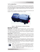
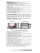
1. Inverter Status Indicator - this green LED illuminates to
provide information on the inverter’s operation.
2. Power Switch - momentary pushbutton switch that turns the
inverter on or off.
3. Negative DC Terminal (black) - the inverter’s connection to
the negative terminal on the battery bank.
4. Positive DC Terminal (red) - the inverter’s connection to the
positive terminal on the battery bank.
5. Input Circuit Breaker - this circuit breaker protects the unit’s
internal wiring and pass-thru relay.
6. Output Circuit Breaker - this circuit breaker provides another
layer of overload protection. This is not a branch-circuit rated
breaker. Separate AC output breakers are required on the output.
7. Mounting Flanges (x4) - secures the inverter to shelf/wall.
8. AC Wiring Compartment - provides access for all AC input
and output connections on the inverter.
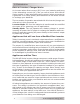
Figure 3, Front and Back Side Features
9. Warning and Information Label - provides pertinent
information for safely using the inverter.
10. REMOTE Port Connection - a RJ11 connector that allows an
optional remote control to be connected.
11. ACCESSORY PORT Connection - a RJ11 connector to allow
the Battery Temperature Sensor (BTS) or MM-AE accessories (e.g.,
MM-DCLD) to be connected.
12. Intake Vent - ventilation openings to pull in air to help keep
the inverter cool for peak performance.
13. Exhaust Vent - ventilation openings that allow heated air to
be removed by the internal cooling fan.
14. Model/Serial Number Label - includes model/serial number
and provides specifi cations and information on the inverter and
charger. See the MM-AE Series Specifi cations on page 34 for
more information and the different models available.
10
11
12
Front Side
9
Back Side
14
13