
Product Manual
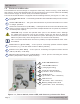
Table Of Contents
- 1.0 Introduction
- 2.0 Installation
- 3.0 Operation
- 4.0 Maintenance and Troubleshooting
- Appendix A – Specifi cations and Optional Equipment
- Appendix B - Battery Information
- Appendix C – Power Consumption and Output Waveforms
- Appendix D – Inverter/Charger Terminology
- Appendix E – Warranty and Service Information

© 2013 Magnum Energy, Inc.
Page vi
List of Figure s
Figure 1-1, Power Switch, Status LED, and Accessory Connection Ports ................................ 3
Figure 1-2, Electrical Connection Points ........................................................................... 4
Figure 1-3, Left Side Features ........................................................................................ 5
Figure 2-1, Simplifi ed Installation Diagram – Single Inverter .............................................. 7
Figure 2-2, Approved Mounting Positions ......................................................................... 9
Figure 2-3, MS-PE Series Dimensions and Side Reference .................................................10
Figure 2-4, DC and Battery Temperature Sensor Wiring ....................................................13
Figure 2-5, Battery Hardware Installation .......................................................................15
Figure 2-6, Inverter DC Hardware Installation .................................................................15
Figure 2-7, Battery Temperature Sensor .........................................................................16
Figure 2-8, AC Terminal Block .......................................................................................19
Figure 2-9, AC Wiring Input/Output ...............................................................................21
Figure 2-10, Grounding System for MS-PE Series .............................................................22
Figure
2-11, Multiple Connections to DC Ground Rod (Method 1) ........................................23
Figure
2-12, Multiple Connections to DC Ground Rod (Method 2) ........................................24
Figure 2-13, Single Connection to DC Ground Rod (Method 3) ...........................................24
Figure 2-14, Neutral-to-Ground Connection (Inverter Mode) ..............................................27
Figure 2-15, Neutral-to-Ground Connection (Standby Mode) ..............................................27
Figure 2-16, Disconnecting the Neutral-to-Ground Connection ...........................................28
Figure 2-17, Large Ground Wire Connected to MS-PE Series ..............................................28
Figure 2-18, Warning Label ...........................................................................................29
Figure 2-19, AC Voltage Checks .....................................................................................30
Figure 3-1, Power Flow - Inverter Mode ..........................................................................31
Figure 3-2, Power Flow - Standby Mode ..........................................................................32
Figure 3-3, Automatic 4-Stage Charging Graph ................................................................33
Figure 3-4, BTS Temperature to Charge Voltage Change ...................................................34
Figure 3-5, Power Switch and Status Indicator .................................................................36
Figure 3-6, Simplifi ed Installation Diagram – Multiple Inverters (in parallel) .........................40
Figure 3-7, Simplifi ed Magnum Panel (AC Panel) ..............................................................41
Figure 3-8, Simplifi ed Magnum Panel (DC Panel) ..............................................................41
Figure 4-1, Performing an Inverter Reset ........................................................................44
Figure B-1, Series Battery Wiring ...................................................................................50
Figure B-2, Parallel Battery Wiring .................................................................................50
Figure B-3, Series-Parallel Battery Wiring .......................................................................50
Figure B-4, Battery Bank Wiring Examples (24-volt) .........................................................51
Figure B-5, Battery Bank Wiring Examples (48-volt) .........................................................52
Figure C-1, AC Waveforms ............................................................................................53
List of Tables
Table 2-1, Recommended DC Wire/Overcurrent Device for Rated Use .................................14
Table 2-2, DC Wire Size For Increased Distance ...............................................................15
Table 2-3, AC Grounding Electrode Conductor Sizing ........................................................23
Table 2-4, Equipment Grounding Conductor Sizing ...........................................................25
Table 3-1, Inverter Battery Turn On/Off Levels .................................................................35
Table 3-2, Inverter/Charger Default Values .....................................................................37
Table 3-3, Inverter Compatibility Level ...........................................................................38
Table 3-4, Remote Compatibility Level ............................................................................38
Table 4-1, Basic Troubleshooting (remote not available) ....................................................43
Table A-1, AC Wiring Color Codes ...................................................................................47
Table A-2, DC Wiring Color Codes ........................................................................................... 47
Table C-1, Typical Appliance Power Consumption ..............................................................53