Operation LTS 15, LTS 17, ProLTS 17 and ProLTS 19 Airless Sprayers 313034H EN - For portable spray applications of architectural paints and coatings. For professional use only- Models 257060, 257065, 24N906, 24N808 3000 psi (21 MPa, 207 bar) Maximum Working Pressure IMPORTANT SAFETY INSTRUCTIONS. Read all warnings and instructions in this manual. Save these instructions. LTS 15 & LTS 17 Models ONLY: Use water-based or mineral spirit-type materials only.
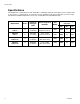
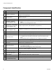
Specifications Specifications This equipment is not intended for use with flammable or combustible materials used in places such as cabinet shops or other “factory”, or fixed locations. If you intend to use this equipment in this type of application, you must comply with NFPA 33 and OSHA requirements for the use of flammable and combustible materials. Model Name 2 Series Dispense Rate gpm (lpm) Hose Length and Diameter Gun Model Maximum Working Pressure PSI MPa bar MAGNUM LTS 15 B 0.27 gpm (1.
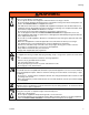
Warnings Warnings The following warnings are for the setup, use, grounding, maintenance and repair of this equipment. The exclamation point symbol alerts you to a general warning and the hazard symbol refers to procedure-specific risks. Refer back to these warnings. Additional, product-specific warnings may be found throughout the body of this manual where applicable. WARNING WARNING GROUNDING This product must be grounded.
Warnings WARNING WARNING FIRE AND EXPLOSION HAZARD Flammable fumes, such as solvent and paint fumes, in work area can ignite or explode. To help prevent fire and explosion: • Do not spray flammable or combustible materials near an open flame or sources of ignition such as cigarettes, motors, and electrical equipment. For LTS 15 and LTS 17 models: only use water-based or mineral spirit-type materials with a flash point greater than 70° F (21° C).
Warnings WARNING WARNING EQUIPMENT MISUSE HAZARD Misuse can cause death or serious injury. • Do not operate the unit when fatigued or under the influence of drugs or alcohol. • Do not exceed the maximum working pressure or temperature rating of the lowest rated system component. See Technical Data in all equipment manuals. • Use fluids and solvents that are compatible with equipment wetted parts. See Technical Data in all equipment manuals. Read fluid and solvent manufacturer’s warnings.
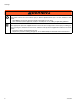
Warnings WARNING WARNING TOXIC FLUID OR FUMES HAZARD Toxic fluids or fumes can cause serious injury or death if splashed in the eyes or on skin, inhaled, or swallowed. • Read MSDS’s to know the specific hazards of the fluids you are using. • Store hazardous fluid in approved containers, and dispose of it according to applicable guidelines.
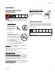
Installation Installation Grounding and Electric Requirements Maintaining grounding continuity when flushing or relieving pressure: hold metal part of the spray gun firmly to the side of a grounded metal pail, then trigger the gun. Sprayer must be grounded. Grounding reduces the risk of static and electric shock by providing an escape wire for electrical current due to static build up or in the event of a short circuit.
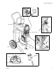
Component Identification Component Identification A Airless spray gun Dispenses fluid. B Power switch Turns sprayer ON and OFF. C Pressure control knob Increases (clockwise) and decreases (counter-clockwise) fluid pressure in pump, hose, and spray gun. C1 Setting Indicator To select function, align symbol on pressure control knob with setting indicator, page 10. D Pump fluid outlet fitting Threaded connection for paint hose.
Component Identification ti9724a U ti9346a B W J F1 F ti9670a X H C C1 G ti9368b L ti9669a E D R S Q V (SG2/SG3) A ti11988a M 313034H T ti11987a 9
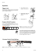
Operation Operation Trigger Lock 2. Turn Prime/Spray valve to PRIME to relieve pressure. Always engage the trigger lock when you stop spraying to prevent the gun from being triggered accidentally by hand or if dropped or bumped. ti9346a 3. Hold gun firmly to side of pail. Trigger the gun to relieve pressure. ti8908a ti8909a ti11986a Trigger Locked Trigger Unlocked 4. Engage trigger lock.
Setup Setup Prime and Flush Storage Fluid 1. Unscrew tip and guard assembly from gun. NOTE: To spray lacquers with the ProLTS 17 and ProLTS 19, you must purchase lacquer conversion kit 256212, and follow priming procedure for oil-based materials. The LTS 15 and LTS 17 units are not intended for lacquers. ti11978a 2. Uncoil hose and connect one end to gun.
Setup flow out of prime tube, into waste pail, for 30 to 60 seconds. 1. Make sure the power switch is OFF and the sprayer is unplugged. 10. Turn power switch OFF. ti2810a 2. Separate prime tube (smaller) from suction tube (larger). ti2810a 11. Transfer suction tube to paint pail and submerge suction tube in paint. ti2039a ti9653a 12. Turn power switch ON. 3. Place prime tube in waste pail. ti5580a ti9652a 4. Submerge suction tube in water or flushing solvent. 13.
Setup Install Tip and Guard on Gun Spraying Techniques Preventing Excessive Tip Wear • 1. Engage trigger lock. • • Spray should be atomized (evenly distributed, no gaps at edges). Start at low pressure setting, increase pressure a little at a time until you see a good spray pattern, without tails. Spray at lowest pressure that atomizes paint. If maximum sprayer pressure is not enough for a good spray pattern, tip is too worn. See Reversible Spray Tip Selection Chart, page 16. ti8908a 2.
Setup Unclogging Spray Tip 4. Unlock trigger lock. Pull trigger to clear clog. To avoid fluid splash-back: • Never pull gun trigger when arrow-shaped handle is between SPRAY and UNCLOG positions. • Tip must be pushed all the way into guard. ti8909a 5. When obstruction is cleared, engage trigger lock and rotate arrow-shaped handle back to SPRAY position. 1. To UNCLOG tip obstruction, engage trigger lock. ti8908a 2. Point arrow-shaped handle backward to UNCLOG position.
Setup Tip Selection Selecting Tip Hole Size Tips come in a variety of hole sizes for spraying a range of fluids. Your sprayer includes an 0.015 in (0.38 mm) tip for use in most spraying applications. Use the following table to determine the range of recommended tip hole sizes for each fluid type. If you need a tip other than the one supplied, see the Reversible Tip Selection Chart on page 16. HINTS: • • As you spray, the tip wears and enlarges.
Setup Reversible Tip Selection Chart Understanding Tip Number The last three digits of tip number (i.e.: 221413) contain information about hole size and fan width on surface when gun is held 12 in. (30.5 cm) from surface being sprayed. First digit when doubled = approximate fan width 413 tip has 8-10 in. fan width 413 tip has a 0.013 in. hole size Tip Part No. Fan Width 12 in. (305 mm) from surface Hole Size 221311 6 - 8 in. (152 - 203 mm) 0.011 in. (0.28 mm) 221411 8 - 10 in. (203 - 254 mm) 0.
Getting Started With Basic Techniques Getting Started With Basic Techniques Use a piece of scrap cardboard to practice these basic spraying techniques before you begin spraying the surface. • Aiming Gun Aim tip of gun at bottom edge of previous stroke, overlapping each stroke by half. Hold gun 12 in. (30 cm) from surface and aim straight at surface. Tilting gun to direct spray angle causes an uneven finish. 12 in.
Shutdown and Cleaning Shutdown and Cleaning Pail Flushing • • • For short term shutdown periods (overnight to two days) refer to Short Term Storage, page 23. For flushing after spraying oil-based coatings, use compatible oil-based flushing fluid or mineral spirits. Read Priming and Flushing Storage Fluid, page 11. For flushing after spraying water-based coatings, use water. Read Priming and Flushing Storage Fluid, page 11 or Power Flush, page 20. 7. Submerge suction tube in water or flushing solvent.
Shutdown and Cleaning NOTE: Step 12 is for returning paint in hose back to paint pail. One 50-ft hose holds approximately 1-quart (1-liter) of paint. 15. Turn prime/spray valve to Prime. 12. To preserve paint in hose: ti9346a a. Point gun into paint pail. b. 16. Turn power switch OFF. Unlock gun trigger lock. 17. Clean InstaClean Fluid Filter and gun, page 22. ti2018a ti8909a c. Pull and hold gun trigger. 18. Fill unit with Pump Armor™ storage fluid. Read Long Term Storage, page 23.
Shutdown and Cleaning Power Flush Power flushing is a faster method of flushing. It can only be used after spraying water-based coatings. 10. Unscrew inlet screen from suction tube. Place inlet screen in waste pail. 1. Relieve pressure, page 10. 2. Remove tip and guard assembly from gun and place in waste pail. 3. Place empty waste and paint pails side by side. ti2040a 11. Connect garden hose to suction tube with Power Flush attachment. Leave prime tube in waste pail. ti9726a 4.
Shutdown and Cleaning NOTE: Step 16 is for returning paint in hose back to paint pail. One 50-ft (15-m) hose holds approximately 1-quart (1-liter) of paint. 19. Turn prime/spray valve to Prime. 16. To preserve paint in hose: a. Point gun into paint pail. ti9346a 20. Turn power switch OFF. b. Unlock gun trigger lock. ti2810a ti8909a c. Pull and hold gun trigger. d. Turn Prime/Spray valve to SPRAY. ti9413a ti9345a 21. Turn off garden hose. Close Power Flush attachment. e. Turn power switch ON.
Shutdown and Cleaning Cleaning Gun Cleaning InstaClean™ Fluid Filter (ProLTS Sprayers Only) • The InstaClean Fluid Filter prevents particles from entering paint hose. After each use, remove and clean it to insure peak performance. Clean gun fluid filter (d) with water or flushing solvent and a brush every time you flush the system. Replace gun filter if damaged. d ti11988a • 1. Relieve pressure, page 10. 2. a. Disconnect airless spray hose (a) from sprayer. b b. Unscrew outlet fitting (b). c c.
Storage Storage Short Term Storage Long Term Storage (up to 2 days) (more than 2 days) 1. Relieve pressure, page 10. NOTE: Always circulate Pump Armor storage fluid through system after cleaning. Water left in sprayer will corrode and damage pump. Follow Shutdown and Cleaning, page 18, or Power Flush Cleaning, page 20. 2. Leave suction tube and prime tube in paint pail. 1. Place suction tube in Pump Armor storage fluid bottle and prime tube in waste pail. ti9353b 3.
Storage 4. Turn pressure control knob clockwise until the pump turns on. 5. When storage fluid comes out of prime tube (5-10 seconds) turn power switch OFF. 6. Turn Prime/Spray valve to SPRAY to keep storage fluid in sprayer during storage.
Storage Stowing Sprayer NOTICE Before storing sprayer make sure all water is drained out of sprayer and hoses. Do not allow water to freeze in sprayer or hose. Do not store sprayer under pressure. 3. Secure a plastic bag around suction tube to catch any drips. 1. Screw inlet screen onto suction tube. 4. Store sprayer indoors. ti9433a ti5552a 2. Coil hose. Leave it connected to sprayer. Wrap hose around hose wrap bracket.
Maintenance and Service Maintenance and Service Tips NOTICE Protect the internal drive parts of this sprayer from water. Openings in shroud allow cooling of mechanical parts and electronics inside. If water gets into these openings, the sprayer could malfunction or be permanently damaged. Caring for Sprayer • • • Keep sprayer and all accessories clean and in good working order. ti2055a Pump Packings ti3388a To avoid overheating motor, keep vent holes in shroud clear for air flow.
Troubleshooting Troubleshooting Check everything in this Troubleshooting Table before you bring the sprayer to a Graco/MAGNUM authorized service center. Problem Power switch is on and sprayer is plugged in, but motor does not run, and pump does not cycle. Cause Solution Pressure is set at zero pressure. Turn pressure control knob clockwise to increase pressure setting. Motor or control is damaged. Take sprayer to Graco/MAGNUM authorized service center. Electric outlet is not providing power.
Troubleshooting Problem Pump does not prime. Cause Solution Prime/Spray Valve is in SPRAY posi- Turn Prime/Spray Valve to PRIME tion. position (pointing down). Inlet screen is clogged or suction tube is not immersed. Clean debris off inlet screen and make sure suction tube is immersed in fluid. Pump was not primed with flushing fluid. Remove suction tube from paint. Prime pump with water or solvent-based flushing fluid, page 11. Inlet screen is clogged or suction tube is not immersed.
Troubleshooting Problem Pump cycles but does not build up pressure. Cause Solution Pump is not primed. Prime pump. Inlet screen is clogged . Clean debris off inlet screen and make sure suction tube is immersed in fluid. Suction tube is not immersed in paint. Make sure suction tube is immersed in paint. Pump cycles, but paint only dribbles or spurts when spray gun is triggered. 313034H Suction tube is leaking. Tighten suction tube connection. Inspect for cracks or vacuum leaks.
Troubleshooting Problem Cause Pressure is set at maximum but can- Reversible spray tip is in UNCLOG not achieve a good spray pattern. position. Spray tip is too large for sprayer. Solution Rotate arrow-shaped handle on spray tip so it points forward in SPRAY position, page 14. Select smaller spray tip. Spray tip is worn beyond capability of Replace spray tip. sprayer. Extension cord is too long or not heavy enough gauge. Replace extension cord. Grounding and Electrical Requirements, page 7.
Troubleshooting Problem Cause Solution Cannot trigger spray gun. Spray gun trigger lock is locked. Rotate trigger safety lever to unlock trigger lock, page 10. Paint is coming out of pressure control switch. Pressure control switch is worn. Take sprayer to Graco/MAGNUM authorized service center. Prime/Spray valve actuates automati- System is over pressurizing. cally relieving pressure through prime tube. Take sprayer to Graco/MAGNUM authorized service center. Paint leaks down outside of pump.
Technical Data Technical Data MAGNUM LTS 15 MAGNUM LTS 17 Working pressure range 0-3000 psi (0-21 MPa, 0-207 bar) 0-3000 psi (0-21 MPa, 0-207 bar) Electric motor 9.0A (open frame, universal) 9.0A (open frame, universal) 1/2 5/8 0.27 gpm (1.02 lpm) 0.31 gpm (1.17 lpm) 1/4 in. x 25 ft (6.4 mm x 7.5 m) 1/4 in. x 25 ft (6.4 mm x 7.5 m) 0.015 in. (0.38 mm) 0.017 in. (0.43 mm) Weight, sprayer only 13.3 lb (6.0 kg) 23.3 lb (10.6 kg) Weight, sprayer, hose & gun 16.5 lb (7.5 kg) 26.5 lb (12.
Technical Data MAGNUM ProLTS 17 MAGNUM ProLTS 19 Working pressure range 0-3000 psi (0-21 MPa, 0-207 bar) 0-3000 psi (0-21 MPa, 0-207 bar) Electric motor 5.8A (open frame, permanent magnet DC) 9.4A (open frame, permanent magnet DC) 3/4 7/8 0.34 gpm (1.29 lpm) 0.38 gpm (1.44 lpm) 1/4 in. x 25 ft (6.4 mm x 7.5 m) 1/4 in. x 50 ft (6.4 mm x 15 m) 0.017 in. (0.43 mm) 0.019 in. (0.
Graco Standard Warranty Graco warrants all equipment referenced in this document which is manufactured by Graco and bearing its name to be free from defects in material and workmanship on the date of sale to the original purchaser for use. With the exception of any special, extended, or limited warranty published by Graco, Graco will, for a period of twelve months from the date of sale, repair or replace any part of the equipment determined by Graco to be defective.