Repair Magnum X5, X7, and ProX9 Airless Sprayer 332694A EN - For portable spray applications of architectural paints and coatings Models 16J750, 16J751, 16W123 IMPORTANT SAFETY INSTRUCTIONS Read all warnings and instructions in this manual. Save these instructions. See page 3 for model series information including dispense rate, recommended hose length, guns, and maximum working pressure. X5 and X7 ONLY: Use water-based or mineral spirit-type materials only.
Table of Contents Table of Contents Table of Contents . . . . . . . . . . . . . . . . . . . . . . . . . . 2 Specifications . . . . . . . . . . . . . . . . . . . . . . . . . . . . . 3 Warnings . . . . . . . . . . . . . . . . . . . . . . . . . . . . . . . . . 4 Component Identification X5 . . . . . . . . . . . . . . . . . 8 Component Identification X7 and ProX9 . . . . . . . 10 Grounding and Electrical Requirements . . . . . . . 12 Thermal Overload . . . . . . . . . . . . . . . . . . . . . . . 12 Operation .
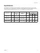
Specifications Specifications This equipment is not intended for use with flammable or combustible materials used in places such as cabinet shops or other “factory”, or fixed locations. If you intend to use this equipment in this type of application, you must comply with NFPA 33 and OSHA requirements for the use of flammable and combustible materials. Model Name Series Maximum Dispense Rate lpm (gpm) Hose Length and Diameter Gun Model Maximum Working Pressure bar MPa PSI Magnum X5 A and B 1.
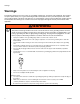
Warnings Warnings The following warnings are for the setup, use, grounding, maintenance, and repair of this equipment. The exclamation point symbol alerts you to a general warning and the hazard symbols refer to procedure-specific risks. When these symbols appear in the body of this manual or on warning labels, refer back to these Warnings. Product-specific hazard symbols and warnings not covered in this section may appear throughout the body of this manual where applicable.
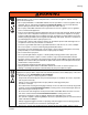
Warnings WARNING WARNING FIRE AND EXPLOSION HAZARD Flammable fumes, such as solvent and paint fumes, in work area can ignite or explode. To help prevent fire and explosion: • Do not spray flammable or combustible materials near an open flame or sources of ignition such as cigarettes, motors, and electrical equipment. For X5 and X7 models: only use water-based or mineral spirit-type materials with a flash point greater than 100° F (38° C).
Warnings WARNING WARNING EQUIPMENT MISUSE HAZARD Misuse can cause death or serious injury. • • Do not operate the unit when fatigued or under the influence of drugs or alcohol. Do not exceed the maximum working pressure or temperature rating of the lowest rated system component. See Technical Data in all equipment manuals. • Use fluids and solvents that are compatible with equipment wetted parts. See Technical Data in all equipment manuals. Read fluid and solvent manufacturer’s warnings.
Warnings WARNING WARNING TOXIC FLUID OR FUMES HAZARD Toxic fluids or fumes can cause serious injury or death if splashed in the eyes or on skin, inhaled, or swallowed. • Read MSDSs to know the specific hazards of the fluids you are using. • Store hazardous fluid in approved containers, and dispose of it according to applicable guidelines.
Component Identification X5 Component Identification X5 A Airless spray gun Dispenses fluid. B Power switch Turns sprayer ON and OFF. C Pressure control knob Increases (clockwise) and decreases (counter-clockwise) fluid pressure in pump, hose, and spray gun. C1 Setting Indicator To select function, align symbol on pressure control knob with setting indicator, page 13. D Pump fluid outlet fitting Threaded connection for paint hose. G Suction tube Draws fluid from paint pail into pump.
Component Identification X5 Component Identification X5 J Z AA AB N B R H S V G Q X T L A D M C1 U C ti22144c 332694A 9
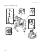
Component Identification X7 and ProX9 Component Identification X7 and ProX9 A Airless spray gun Dispenses fluid. B Power switch Turns sprayer ON and OFF. C Pressure control knob Increases (clockwise) and decreases (counter-clockwise) fluid pressure in pump, hose, and spray gun. C1 Setting Indicator To select function, align symbol on pressure control knob with setting indicator, page 13. D Pump fluid outlet fitting Threaded connection for paint hose.
Component Identification X7 and ProX9 Component Identification X7 and ProX9 ProX9 Shown W ti9346a B J AA ti22077a K F C F1 H Y G ti9670a ti22167a AC L AB Z U X R D A S C1 E M V ti9669a Q ti22177a T ti22176a 332694A 11
Grounding and Electrical Requirements Grounding and Electrical Requirements Fluid supply container: follow local code. Sprayer must be grounded. Grounding reduces the risk of static and electric shock by providing an escape wire for electrical current due to static build up or in the event of a short circuit. • • Grounding the metal pail: connect a ground wire to the pail by clamping one end to pail and other end to ground such as a water pipe.
Operation Operation See Operation manual for basic information on sprayer setup, flushing, and storage. 2. Move Prime/Spray valve to PRIME to relieve pressure. Trigger Lock Always engage the trigger lock when you stop spraying to prevent the gun from being triggered accidentally by hand or if dropped or bumped. ti9346a ti13961a A20 Only 3. Hold gun firmly to side of pail. Trigger the gun to relieve pressure. ti8908a ti8909a Trigger Locked Trigger Unlocked ti9207a Pressure Relief Procedure 4.
General Repair Information General Repair Information Flammable materials spilled on hot, bare, motor could cause fire or explosion. To reduce risk of burns, fire or explosion, do not operate sprayer with cover removed. • Keep all screws, nuts, washers, gaskets, and electrical fittings removed during repair procedures. These parts usually are not provided with replacement kits. • Test repairs after problems are corrected.
Basic Troubleshooting Basic Troubleshooting Check everything in this Basic Troubleshooting table before you bring the sprayer to a Graco/MAGNUM authorized service center. Problem Power switch is on and sprayer is plugged in, but motor does not run, and pump does not cycle. Cause Solution Pressure is set at zero pressure. Turn pressure control knob clockwise to increase pressure setting. Motor or control is damaged. Take sprayer to Graco/MAGNUM authorized service center.
Basic Troubleshooting Problem Pump does not prime. Cause Solution Prime/Spray Valve is in SPRAY posi- Move Prime/Spray Valve to PRIME tion. position. Inlet screen is clogged or suction tube is not immersed in fluid. Clean debris off inlet screen and make sure suction tube is immersed in fluid. Pump was not primed with flushing fluid. Remove suction tube from paint. Prime pump with water or solvent-based flushing fluid, see Operation manual. Inlet valve check ball is stuck.
Basic Troubleshooting Problem Pump cycles but does not build up pressure. Pump cycles, but paint only dribbles or spurts when spray gun is triggered. 332694A Cause Solution Pump is not primed. Prime pump. Inlet screen is clogged. Clean debris off inlet screen and make sure suction tube is immersed in fluid. Suction tube is not immersed in paint. Make sure suction tube is immersed in paint. Suction tube is leaking. Tighten suction tube connection. Inspect for cracks or vacuum leaks.
Basic Troubleshooting Problem Cause Pressure is set at maximum but can- Reversible spray tip is in UNCLOG not achieve a good spray pattern. position. Spray tip is too large for sprayer. Solution Rotate arrow-shaped handle on spray tip so it points forward in SPRAY position, see Operation manual. Select smaller spray tip. Spray tip is worn beyond capability of Replace spray tip. sprayer. Extension cord is too long or not heavy enough gauge. Replace extension cord.
Basic Troubleshooting Problem Cause Fan pattern varies dramatically while Pressure control switch is worn and causing excessive pressure variaspraying. tion. OR Solution Take sprayer to Graco/MAGNUM authorized service center. Sprayer does not turn on promptly when resuming spraying. Cannot trigger spray gun. Spray gun trigger lock is locked. Rotate trigger safety lever to unlock trigger lock, page 13. Paint is coming out of pressure control switch. Pressure control switch is worn.
Advanced Troubleshooting Advanced Troubleshooting See Basic Troubleshooting first, page 15 for problems that are more easily remedied. Motor Does Not Operate Specific Problem Basic mechanical problems. 20 Cause Solution Paint is frozen or hardened in pump. See Basic Troubleshooting, page 15. Gears are damaged. Remove motor enclosure and rotate motor fan to check for bad gears. If gears bind or slip, remove pump cover and replace failed gears. See List of Kits, page 30.
Advanced Troubleshooting Specific Problem Basic electrical problems. Cause Solution Motor overheated. Allow motor to cool for 45 minutes. Retry. Electrical outlet is damaged. Reset building circuit breaker or replace fuse. Try another outlet. Check electric supply with volt meter. Meter must read 220/240 VAC. If voltage is too high, do not plug sprayer in until outlet is corrected. Control board leads are improperly fastened, improperly mated, or corroded. Replace any loose terminals.
Advanced Troubleshooting Specific Problem Sprayer wiring problems. Cause Solution Sprayer power cord damaged. 1. Unplug sprayer power cord. 2. Disconnect brown and blue power cord wires at EMI filter. NOTE: Remove enclosure mounting screws and pull enclosure away from drive housing. Take care not to pull on leads from electrical cord and power switch. 3. Plug in power cord. 4. Test voltage between brown and blue wires of power cord. Meter must read 220-240 VAC. 5. Replace power cord if no voltage.
Advanced Troubleshooting Circuit Breaker is Tripping Specific Problem Building circuit breaker opens as soon as sprayer is turned on. NOTE: Remove enclosure mounting screws and pull enclosure away from drive housing. Take care not to pull on leads from electrical cord and power switch. Cause Sprayer electrical wiring is pinched or insulation is damaged. Repair or replace any damaged wiring or terminals. Securely reconnect wires. Wires between pressure control switch and control board are pinched.
Advanced Troubleshooting Erratic Motor Operation Specific Problem Sprayer quits after running for 5 to 10 minutes. Cause Solution Building circuit is overloaded. Remove other loads from building circuit or find another circuit that has less load. See Grounding and Electrical Requirements, page 12. Electrical outlet supplying wrong voltage. Try another outlet. Check electric supply with volt meter. Meter must read 220-240 VAC. If voltage is too high, do not use outlet until corrected.
Advanced Troubleshooting Low or Fluctuating Output Specific Problem Cause Solution Pump cycles, but output is low or See Basic Troubleshooting, surging. page 15. Worn or obstructed inlet and outlet valves. Check for worn pump valves as follows: Prime sprayer with paint. Turn the Prime/Spray valve to SPRAY position. Turn pressure control fully clockwise. Trigger spray gun briefly. When spray gun trigger is released pump should cycle momentarily and stop.
Advanced Troubleshooting Specific Problem Cause Solution Motor runs and pump cycles, but Intake valve or outlet valve is not Remove and clean inlet valves and outlet valves. pressure does not build up. seating properly. Replace if necessary. See List of Kits, page 30. Pump packings are worn or damaged. Check for leaking around pump. ProX9: Replace pump packings. See List of Kits, page 30. X5 and X7: Replace complete pump. See List of Kits, page 30.
Motor Diagnostics Motor Diagnostics X5 and X7 ProX9 Motor Diagnostics reveal a damaged motor or if motor brushes are shorter than 1/4 in. (6.4 mm) replace the motor using Motor Kit. See List of Kits, page 30. Check for electrical continuity in motor armature, windings and brush as follows: Setup If Motor Diagnostics reveal a damaged motor or if motor brushes are shorter than 1/4 in. (6.4 mm) or if the motor shaft cannot turn, replace the motor using Motor Kit. See List of Kits, page 30. 1.
Pressure Control Switch Diagnostics Pressure Control Switch Diagnostics 1. Unplug power cord and Relieve Pressure. See Pressure Relief Procedure, page 13. 2. If paint is leaking from pressure control switch between pressure control knob and base, replace pressure control switch. 3. ProX9: Remove front cover, yoke, and pins. Disconnect pressure control switch connector from control board. X5 and X7: Remove enclosure and disconnect pressure control switch connector from control board.
Control Board Diagnostics Control Board Diagnostics ProX9 X5 and X7 NOTE: Check for motor problems before replacing control board. A damaged motor may burn out a good control board. NOTE: Check for motor problems before replacing control board. A damaged motor may burn out a good control board. Check for a damaged control board or pressure control switch as follows: 1. Relieve Pressure (see Pressure Relief Procedure, page 13). 2. Unplug electrical cord. 3. Remove four cover screws and front cover.
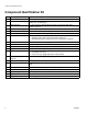
List of Kits List of Kits Kit Number 16G223 16W944 122893 16K624 16X021 16W942 16F629 16W945 247339 247340 257566 245673 16E839 257569 257568 16W946 16W947 16G226 16X876 16X877 289107 246286 16E844 16X380 16E845 243094 288747 16F047 288818 243012 197607 16D951 15J801 244035 235014 16G228 256938 16E778 289102 16G227 16W941 256212 30 Models X5 and X7 ProX9 ProX9 X5 Series Z and X7 Series A X5 Series Z and X7 Series A ProX9 X5 and X7 ProX9 X5 X7 and ProX9 X5 and X7 ProX9 X5 X7 X7 ProX9 ProX9 X5 Series Z and
Notes Notes 332694A 31
Parts Parts Magnum X5 Pump Model 16J750 (Series A and B) 4 2 55 8 31 73 5 74 9 1 18 7 17 1f 1a 1b 1c 1e 1d 16 72c 72a 72b 72 36 70 30 66 67 66 ti17725c 37 38 32 332694A
Parts Parts List Magnum X5 Model 16J750 (Series A and B) Ref.
Parts Magnum X5 Frame (Series A) Model 16J750 (Series A) 115 12 10 102 51 50 57 52 125 56 11 4 39 121 11 122 6 52 123 53 22a 22b 41 40 ti22526a 34 332694A
Parts Parts List Magnum X5 Model 16J750 (Series A) Ref. Part 4 6 9 112689 SCREW 16D684 FRAME 115498 SCREW, mach, slot hex wash hd (not shown) 16K624 KIT, repair, enclosure, X5 and X7 series A (includes 11, 17, 39) 115477 SCREW, mach, torx pan hd 118899 SWITCH, rocker, spdt 120724 SCREW (not shown) 16E839 KIT, repair, stand 16G226 KIT, repair, cordset 16J789 CORD SET, 2 m, Australia 16G226 CORD SET, 2 m, Europe 16T398 LABEL, warning 247339 HOSE, cpld, 1/4 in.
Parts Magnum X5 Frame (Series B) Model 16J750 (Series B) 39 121 12 57 51 56 251 52 57 57 50 22 52 52 125 109 4 41 11 53 11 54 40 19 ti22527a 36 332694A
Parts Parts List Magnum X5 Model 16J750 (Series B) Ref. Part 4 6 9 112689 SCREW 16D684 FRAME 115498 SCREW, mach, slot hex wash hd (not shown) 16X021 KIT, repair, enclosure, X5 and X7 series B (includes 11, 17, 39) 115477 SCREW, mach, torx pan hd 118899 SWITCH, rocker, spdt 120724 SCREW (not shown) 16E839 KIT, repair, stand 16X876 KIT, repair, cordset 195793 LABEL, warning 247339 HOSE, cpld, 1/4 in. x 25 ft 243011 KIT, accessory, gun, SG3 10 11 12 17 19 22 39▲ 40 41 332694A Description Qty. Ref.
Parts Magnum X7 Pump Model 16J751 (Series A and B) 5 63 8 2 31 73 1 1f 4 9 7 16 1a 1e 17 18 1b 1c 1d 72c 72a 72b 101 ti17724c 72 74 68 70 66 67 36 30 66 38 37 38 332694A
Parts Parts List Magnum X7 Model 16J751 (Series A and B) Ref.
Parts Magnum X7 Frame (Series A) Model 16J751 (Series A) 115 12 10 58 102 39 65 11 22a 125 121 22b 64 122 59 6 123 60 11 61 56 55 4 57 54 21 51 52 41 53 40 ti22538a 20 40 332694A
Parts Parts List Magnum X7 Model 16J751 (Series A) Ref.
Parts Magnum X7 Frame (Series B) Model 16J751 (Series B) 56 39 10 12 58 59 55 65 109 64 250 4 125 60 22 10 11 61 121 6 65 57 54 57 11 52 51 20 21 ti22534a 42 53 332694A
Parts Parts List Magnum X7 Model 16J751 (Series B) Ref. Part 4 6 10 112689 SCREW, button HD 16D685 FRAME 16X021 KIT, repair, enclosure, X5 and X7, Series B (includes 11, 17, 39) 115477 SCREW, mach, torx pan hd 118899 SWITCH, rocker, spdt 120724 SCREW (not shown) 257569 KIT, leg, left (includes 54) 257568 KIT, leg, right (includes 54) 16X876 KIT, repair, cordset 195793 LABEL, warning 247339 HOSE, cpld, 1/4 in.
Parts Magnum ProX9 Pump Model 16W123 26 27 28 41 50 5 40 32 74 33 61 76 52 88 39 21 81 87 64 82 30 37 31 83 53 85 43 34 92 93 46 15 12 86 90 91 62 252 14 29 61 11 35 60 23 13 16 17 36 ti22537a 18 10 44 332694A
Parts Parts List Magnum ProX9 Model 16W123 Ref. Part 5 10 11 12 13 14 15 16 17 18 21 23 26 27 16D576 245673 15E813 15B652 15J801 103413 115099 195108 195400 244035 289102 247339 118899 16W942 28 29 30 31 32 33 34 35 36 37 39 40 41 43 Description LABEL,made in USA STRAINER, 3/4-16 unf NUT, jam WASHER, suction TUBE, suction, intake PACKING, o-ring WASHER, garden hose TUBE, drain CLIP, spring DEFLECTOR, barbed KIT, repair, gear and yoke HOSE, cpld,1/4 in.
Parts Magnum ProX9 Frame Model 16W123 6 9 4 1 45 42 44 43 3 2 ti22459a 8 46 332694A
Parts Parts List Magnum ProX9 Model 16W123 Ref. Part Description 1 2 3 4 6 7 16W947 16W946 16W362 16W200 257326 256993 KIT, repair, right leg (includes 43) KIT, repair, left leg (includes 43) AXLE, cart SHELF, motor RACK, hose HANDLE, painted 332694A Qty. 1 1 1 1 1 1 Ref. Part Description 8 9 42 43 44 45 112612 120689 115094 260212 120788 115480 CAP, hub NUT, hex, acorn, 5/16-18, nickel WHEEL, 10 in. SCREW, hex washer, hd, thd form SCREW, carriage KNOB, t-handle Qty.
Wiring Diagram Wiring Diagram Magnum X5 (Series A) and X7 (Series A) Models 16J750 (Series A) and 16J751 (Series A) 9 Ref ON/OFF Switch Power Cord Green Wire Power Cord Brown Wire Power Cord Blue Wire Black Motor Lead Black Motor Lead ti16291a 48 332694A
Wiring Diagram Magnum X5 (Series B) and X7 (Series B) Models 16J750 (Series B), 16J751 (Series B) Power Cord Blue Wire ON/OFF Switch Power Cord Brown Wire Power Cord Green Wire Pressure Control Ref.
Wiring Diagram Magnum ProX9 Model 16W123 Power Switch Brown Wire Motor AutoPrime Blue Wire Brown Wire Pressure Control Green/Yellow Wire ti22243b 50 332694A
Technical Data Technical Data Magnum X5 Working pressure range Electric Motor Operating horsepower Maximum delivery (with tip) Paint hose Maximum tip hole size Magnum X7 Magnum ProX9 0-207 BAR, 0-21 Mpa (0-3000 psi) 4.5A (open frame, universal) 6.5A (open frame, permanent magnet DC) 1/2 5/8 7/8 1.02 lpm (0.27 gpm) 1.17 lpm (0.31 gpm) 1.44 lpm (0.38 gpm) 6.4mm x 7.5 m (1/4 in. x 25 ft) 6.4mm X 15 m (1/4 in. x 50 ft) 0.015 in. (0.38 mm) 0.017 in. (0.43 mm) 0.019 in. (0.48 mm) 5.
Graco Standard Warranty Graco warrants all equipment referenced in this document which is manufactured by Graco and bearing its name to be free from defects in material and workmanship on the date of sale to the original purchaser for use. With the exception of any special, extended, or limited warranty published by Graco, Graco will, for a period of twelve months from the date of sale, repair or replace any part of the equipment determined by Graco to be defective.