Installation Instructions for: INTERCOOLED SUPERCHARGER SYSTEM 2005-2006 PONTIAC GTO LS2 Step-by-step instructions for installing the best in supercharger systems. Magnuson Products Inc 1990 Knoll Drive, Ventura, CA 93003 (805) 642-8833 * (805) 677-4897 fax magnusonproducts.com * magnacharger.com 89-89-60-014 Rev B .
INSTALLATION MANUAL Magna Charger GM 6.0 LS2 Liter Engines, 2005 and later Pontiac GTO Please take a few moments to review this manual thoroughly before you begin work, as there are special steps for both the LS1 (2004) and LS2 (2005-on) equipped vehicles: Μake quick parts check to make certain your kit is complete (see shipper parts list in this package). If you discover shipping damage or shortage, please call our office immediately.
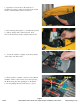
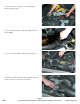
1. Open the hood and remove the under hood insulation by prying out the seven plastic buttons that retain it. The insulation will not be reused. 2. Disconnecting the negative (-) and then the positive (+) battery clamps with a 13mm wrench. Next, remove the the battery anchor and the battery itself. 3. Locate the vehicles computer on the front surfase of the driver side wheel well. 4. There are three computer connectors, Grey, Black and Blue.
5. The computer connectors can be removed when the latch is pushed down and the red tail of the latch is visible on the end of the connector. Latch tail 6. Remove the two T20 TORX screws that secure the computer to its mounting bracket. 7. Remove the computer carefully from the vehicle. 8. Here are the shipping materials supplied to quickley return the vehicle computer to Magnuson Products Inc. 12/05 Page 4 2005-2006 Pontiac GTO LS2 Supercharger Installation Instructions magnacharger.
9. Place the computer into the plastic bag supplied and then wrap it in the bubble-pack sheet and seal the box. 10. Completely fill out the pre-paid shipping form supplied and then remove the adhesive label on the third page, placing it on the top of the box. Take the box to your nearest UPS office to be returned to Magnuson Products Inc. Magnuson will then re-program the computer and quickly return it to you via UPS. 11.
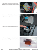
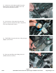
13. Remove the two engine covers by pulling up firmly along the edges. 14. Loosen the Air Tube clamp at the Mass Air Flow meter (MAF). 15. Loosen the Air Tube clamp at the throttle body. 16. Remove the PCV tube from the air tube and from where it connects to the valve cover barb. 12/05 Page 6 2005-2006 Pontiac GTO LS2 Supercharger Installation Instructions magnacharger.
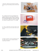
17. Remove the air tube completely, it will not be reused. 18. Disconnect the Electronic Throttle Control (ETC) connector on the right side. 19. Remove the PCV hose that connects the intake manifold to the engine valley cover vent. 20. Disconnect the eight fuel injector connectors by pulling up on the grey release latches and the squeezing them at the top. Remove the injector harness clips from the intake manifold.
21. At the front of the intake manifold locate the Manifold Absolute Pressure (MAP) sensor and disconnect the electrical connector. 22. On both sides of the engine disconnect the ignition coil pack connectors fron the coil packs by first removing the blue lock key. 23. The EVAP is located at the front of the passenger (Right) cylinder head. 24. Disconnect the Evaporative Purge Solenoid (EVAP) electrical connector.
25. Remove the EVAP line at the firewall by squeezing on the connector and pulling it free. 26. Remove the EVAP tube connector from the intake manifold by pushing in on the white release trigger and pulling firmly. 27. Remove the vacuum acessory hose and connector from the rear of the manifold. Vacuum accessory hose 28. On the left side of the intake manifold, locate the fuel pressure test port.
29. Remove the fuel line from the fuel rail by first prying the lock clip free with a small screwdriver. Use the supplied removal tool to remove the fuel line connector. Lock clip Tool 30. Remove the intake manifold by loosening the ten manifold bolts with a socket wrench and a 8mm socket. Manifold bolts 31. Remove the intake manifold, fuel system and throttle body assembly. 32. Use a shop vacuum cleaner to remove any debris or dirt from the intake port area and engine valley cover.
33. Cover the intake ports with tape or clean rags to keep dirt and debris from entering the engine. 34. Reove the coolant vent hose from the vent pipe. Coolant vent hose 35. Remove the coolant vent pipe by removing the attachment bolts with a 10mm socket wrench. 36. Remove the coolant vent pipe. Ensure that the Oring gaskets under the vent pipe blocks do not stick to the cylinder heads. If so, remove them as new gaskets are supplied.
37. Install the new vent pipe O-ring gaskets using the supplied grease to hold them in place. 38. Install the new vent pipe with the supplied bolts and torque them with a torque wrench and 10mm socket to 106 in-lbs. 39. Remove the accessory serpentine belt by rotating the tensioner bolt with a 15mm wrench. Release the slack and then pull the belt off the tensioner pulley. 40. Remove the stock belt tensioner assembly by removing the two mounting bolts with a 15mm socket wrench.
41. Install the new tensioner assembly in place of the stock unit with the supplied bolts and torque them to 40 ft-lbs. 42. Remove the engine oil pressure sensor connector from the pressure sensor located at the rear of the valley cover. 43. Remove the engine oil pressure sensor from the valley cover with a 28mm wrench. 44. Remove the engine valley cover and gasket by removing the ten bolts with a ratchet and 13mm socket.
45. The gasket will be reused, the original valley cover and bolts will not. Inspect the gasket for any damage and then reinstall, note that it will only fit correctly in one position. 46. Using a small straight blade screwdriver, remove the 8 O-rings from the underside of the engine valley cover and transfer them to the grooves in the bottom of the new cover. 47. Install the new engine valley cover and flathead bolts supplied with a 5mm Allen socket and torque the bolts to 18 lb-ft.
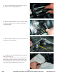
49. Re-connect the oil pressure transmitter electrical connector. 50. Re-install the oil pressure sensor and torque it to 15 ft-lbs. Re-attach the sensor electrical connector. 51. Remove the engine lift bracket from the rear of the right cylinder head by removing its two mounting bolts with a 15mm wrench. 52. The automatic transmission fill tube will need to be moved slighly outward to avoid contact with the supercharger fuel cross-over pipe.
53. Vehicles with automatic transmission only. Manual transmission vehicles please skip to step the next. Move the automatic transmission fill tube by pulling it firmly outward towards the fender of the vehicle. It will only be necessary to move the tube 1/ 4”- 3/8”. After installing the supercharger and manifold assembly, check for contact between the fill tube and the fuel cross-over pipe. Move fill tube 54. Remove the throttle body by removing the four mounting bolts with a 10mm socket wrench. 55.
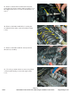
57. Remove the MAF from the airbox by loosening the connector clamp. 58. Pull back the grey locking latch on the MAF electrical connector and then squeeze the connector to remove it. 59. Remove the tape and split loom from the harness to about 6” below the MAF connector. Locate the Brown/Yellow and the solid Brown wires. These are the Intake Air Temperature (IAT) sensor wires on the connector. Cut these two wires approximately 2” below the connector. To connector not used To computer 60.
61. Using the new Intake Air Tempeture (IAT) harness and crimp/shrink connectors supplied, connect the white 62”wires to either white wire of the new IAT harness. Strip about ¼” of insulation from the ends of the IAT harness, then crimp the connectors on. Using a heat gun or blow dryer set on HIGH; shrink the insulation on the connectors so that it contracts around the wires completely. You must shrink the insulation, as crimping the connectors alone is not enough to secure them! 62.
65. Locate the MAP connector on the harness. Remove the black tape and split loom from the MAP connector and wires. Viewing the connector from the top or clip side note the location and colors of the three wires on the connector, Purple/White left, Green center and Black on the right. Approximately 1” behind the connector cut these three wires. 66. Install the new MAP harness to the Purple/White, Green and Black wires using the crimp/shrink connectors supplied.
69. Install the MAP sensor in its new location using the supplied bracket and the button head Allen screw with a 4mm Allen wrench. 70. Install the fuel manifold O-ring into the recess on the fuel rail with some of the grease supplied. Next install the fuel manifold using a 4mm Allen socket and torque wrench. Torque the manifold fasteners to 106in-lbs. 71. Install the two intake manifold gaskets supplied onto the recesses in the manifold face. Ensure that the gaskets are fully seated in recesses. 72.
73. With the help of a assistant carefully set the supercharger and manifold assembly in place. Do not use the black plastic bypass cannister as a lifting point. This is pre-set from the factory and can be damaged if you lift with it. 74. Remove the split-looms that support some of the manifold to cylinder head bolts. Start all ten bolts by hand to ensure proper alignment of the manifold. 75. Torque all ten bolts that secure the manifold to the cylinder heads gradually and evenly to a torque of 89 in-lbs.
Clearance between fill tube and fuel cross-over pipe 77. Ensure that there is clearance between the transmission fill tube and the fuel cross-over pipe. 78. Install the coil pack connectors and blue lock keys on both sides of the engine. 79. At the rear of the supercharger on the passenger side, plug in the new MAP and IAT connections. 80. Install the eight Injector Wiring Adaptors on to the harness fuel injectors connectors.
Cut-away 81. Install the Injector Wiring Adaptors on all eight fuel injectors. Note that the cut-away side of the connector goes towards the top of the injector. 82. Locate the two hard plastic EVAP lines previously removed. 83. Using a sharp shop knife, cut the hard plastic tube where it covers the the barbed end of the EVAP fittings. Take care not to damage the fittings as they will be reused. Test port fitting 84. Using the piece of 5/16” EVAP hose supplied cut it into two pieces.
85. Connect the long EVAP hose with the Test port fitting to the fire wall connection. Route the other end of the hose forward between the driver side coil pack and the fuel rail. Pass the hose under the inlet maifold and supercharger drive to the EVAP purge solenoid. 86. Re-connect the Purge solenoid electrical connection, then install the right angle fitting of the long EVAP hose to the top connection of the Purge solenoid.
Vacuum accessory line Barb 89. Connect the new vacuum accessory line to the small barb on the left side of th inlet manifold. 90. Connect the fuel line to the fitting on the fuel manifold and secure it with the lock clip. 91. Unclip the steam vent line from the back of the electric cooling fan shroud. 92. Route the vent line down under the tensioner mounting bracket to the steam vent pipe barb. Trim the vent hose to length and attach it to the vent pipe barb.
ETC Connector 93. Remove the tape and split loom from the harness to about 6” below the Electric Throttle Control (ETC) connector. Cut all these wires approximately 2” below the connector. 94. Using the color coded lengths of wire and crimp/ shrink connectors supplied supplied, extend the six throttle body connector wires. Be sure to correctly match the extention wire color to the harness and at the throttle body connector. Strip about ¼” of insulation from the ends of all the wires.
97. Using a long 15mm wrench to compress the tensioner, install the new belt using the diagram above. 98. Unclip the small coolant hose from the top of the air box. Unscrew the three cross-head fasteners that secure the airbox cover with a cross head screwdriver and set the cover to one side. Air box fasteners 99. Remove the stock air filter element and discard it. 100. Replace the stock filter element with the K&N air filter element supplied.
101. Replace the air box cover, tighten the three fasteners and place the K&N “Warning” label on the cover. Warning label 102. Here is the new air tube and mounting components. 103. Install the hose connector and bellows on the air tube with the clamps supplied. 104. Attach the bellows end of the air tube on the air meter. 12/05 Page 28 2005-2006 Pontiac GTO LS2 Supercharger Installation Instructions magnacharger.
105. Attach the hose end of the air tube to the throttle body. Tighten all clamps securely. 106. Install the PCV inlet hose. Cut a 16” length length of 3/8” hose supplied and attach one end to the barb on the right valve cover. Attach the other end of the hose to the barb on the bottom of the new air tube. Air tube PCV barb 107. Assemble the PCV outlet hose by cutting a 18” length of the 3/8” hose. Attach one end the hose to the left valve cover PCV barb. PCV barb 108.
109. At the rear of the left valve cover, remove the black rubber cap from the PCV barb. Connect the end of the PCV outlet hose to this barb. PCV barb 110. Insert the new check valve into the 11/32” brake hose. 111. Install the check valve into the grommet on the brake booster. 112. Connect the end of the brake booster hose to the upper barb on the driver side of the inlet manifold. 12/05 Page 30 2005-2006 Pontiac GTO LS2 Supercharger Installation Instructions magnacharger.
113. Remove the two push-lock fasteners that secure the back edge of the lower splash shield. Do this by prying up on the center of the fastener with a small straight blade screwdriver and then removing the fastener completely. 114. Remove the five push-lock fasteners and the radiator shield. 115 Remove the three screws that secure the front fascia or “nose” of the vehicle with a cross-head screwdriver. Fascia screws 116. Remove the two screw in each wheel well that secure the front fascia.
117. Pull out on the wheel well edge of the front fascia. Pull out 118. Push the front fascia forward and then pull out at the edge of the fascia below the head light on both sides to free the locking tab. Pull out Locking tab Push forward 119. Disconnect the fascia electrical connection located on the driver side. 120. Remove the fascia complete. 12/05 Page 32 2005-2006 Pontiac GTO LS2 Supercharger Installation Instructions magnacharger.
121. This is a diagram of the complete intercooler system plumbing. Note the routing of the hoses and their connections. Out In 122. Remove the fluid supply hose from the pump and then temporarily cap the pump nipple with the rubber cap supplied. Depress the wire clip on the electrical connector to remove it from the pump. 123. Remove the bolt that secures the rear of the reservoir bolt with a 10mm socket wrench. 124. Remove the yellow filler cap from the neck of the reservoir.
125. Remove the push-lock fastener that secures the bottom of the reservoir to the splash shield. 126. Remove the reservoir by rotating it 90 degrees and lowering it down and out. 127. Install the intercooler pump relay harness by removing the cover of the Fuse/Relay center on the right hand side of the engine compartment. Remove the fourth 15amp fuse from the top marked “AUTO TRANS” temporarily from the base. 128. Place one leg of the 15 amp fuse through the Fuse-Tap supplied.
129. Install the fuse and Fuse-tap back into its original location. On the end of the yellow wire from the relay harness, strip the insulation back 1/4” and crimp on the female spade terminal. Connect the female spade terminal to the male spade of the Fuse-Tap. 130. Connect the Black ground (-) wire with the ring terminal to the chassis ground connection located just below the Cruise Control module platform. Remove the nut with a 10mm wrench and place the ring terminal on the stud.
133. Route the pump harness and connector down to the pump through the harness hole next to the battery platform. Pump harness 3.750” 134. Mount the intercooler coolant pump on the outside of the frame rail just ahead the where the reservoir was located using the two Adel clamps and selftapping screws. Drill two 1/4” holes in the locations shown for the self-tapping screws. Note the position of the pump inlet, outlet and electrical connections. Plug the pump harness connector into the end of the pump.
137. Using a sharp knife or hole-saw make two 11/8” holes in the side from the back side of the splash shield. This can be easily done by pulling down on the bottom edge of the front fascia or ”Nose” cover. 138. Assemble the heat exchanger by peeling the backing paper off the two short plastic strips and apply them to the inside of the upper mounts. 139. Apply the longer third strip to the left front face of the heat exchanger 4-1/2” from the top edge as shown. 140.
141. The intercooler fluid reservoir will attach to the top of the battery with adhesive backed velcro strips. Clean the bottom of the coolant reservoir with lacquer thinner, as it must be very clean for the adhesive to attach. Clean the top of the battery as well. Reservoir color may vary. 142. Cut the 15” length of Velcro supplied into six pieces 2-1/2” long. Peel off the paper backing and install three pieces of Velcro onto the bottom of the reservoir as shown. 143.
145. Install the trimmed elbow hose to the lower barb on the reservoir. Secure the hose with a #10 clamp. 146. Place the intercooler reservoir on the top of the battery. Ensure that the Velcro has a good “grip”. 147. Lower the front heat exchanger into place on the front of the A/C condenser. As you lower the heat exchanger and hoses into place, pull the black A/C dryer cylinder forward on the left side to allow the heat exchanger to pass and the upper brackets to sit flat on the top of the A/C condenser.
149. Route the elbow hose from the lower barb of the reservoir down to inlet of the coolant pump. Hose to heat exchanger Washer reservoir Hose from coolant reservoir 150. Connect the hose from the lower heat exchanger barb to the outlet on the pump through the new hole in the splash shield. Secure the hose with #10 clamps. 151. Route the hose from the upper barb down through the new hole in the right side of the splash shield.
153. Re-install the fascia by first reconnecting the electrical connection. Snap the locking tabs back into place below the headlights and then replace the upper mounting screws. 154. Replace the upper radiator and lower splash shields with the push-lock fasteners that secure them. 155. Fill the intercooler reservoir with a 50/50 mixture of GM recommended engine coolant and distilled or de-ionized water only. The intercooler system will hold approximately 2 gallons (8 liters).
157. Remove the FUSE/RELAY center cover and using the Magnavolt as a template, drill two 5/16” hole along the top edge to mount the Magnavolt unit. 158. Assemble the Magnavolt unit to the Fuse/Relay center cover by placing the rubber mounts into the two holes in the cover and then place the magnavolt on the rubber mounts. Secure the mounts with the nuts supplied and tighten them with a 10mm wrench. 159.
161. Replace the cover with the Magnavolt attached on to the Fuse/Relay center. Connect the Magnavolt harness to the unit. 162. On the passenger side shock tower, locate the circular wire conduit. Cut the Ty-strap where it meets the Fuse/Relay center. Using a small straight blade screwdriver, genly pry the locking tabs free on the upper cover of the conduit to free the cover. Magnavolt harness Fuse/Relay cover Conduit cover tab Cut Ty-strap 163.
165. Using the length of solid white wire and the Crimp/Shrink connector provided, extend the white wire of the Magnavolt harness. Cover the white wire with the split-loom provided and carefully route the wire along the firewall, behind the supercharger to the computer area on the driver side wheel well. BLUE computer connector 166. Peel back the black electrical tape and Splitloom from the BLUE computer connector. Locate the BROWN/RED wire. BROWN/RED wire 167.
169. Install the length of 5/32” vacuum hose onto the Magnavolt hose using the black plastic hose connector. 170. Route the wire along the firewall, behind the supercharger to the manifold barb at the left rear of the supercharger manifold. Secure the hose and extended white wire as necessary with the Ty-straps provided. Hose connector Manifold barb Magnavolt hose 171. Install the re-programed computer on its bracket using the two T20 TORX screws . 172.
173. Locate the plastic cross-head screw in the rain gutter to the right of the center windshield wiper. Remove the screw with a screwdriver. From the underside in the engine compartment, push the screw base up and out so that just the hole in the rain gutter remains. 174. Using a small straight blade screwdriver, open the harness clamp and pull the harness free. 175. Remove the harness clamp from the firewall, it will not be re-used. 176.
177. Install the harness clamp around the harness, hoses and cables directly behind the supercharger assembly. Take care that nothing can come in contact with the rear drive belt and pulleys. Secure the new clamp with the supplied bolt and nut in the rain gutter hole. Tighten them securely with a 10mm wrench. 178. Re-connecting the negative (-) and then the positive (+) battery clamps with a 13mm wrench. 179. Reinstall the shock tower brace with its fasteners into the original position.
181. On the left side engine cover trim the cover as shown. A little more care must be used on trimming this cover as you must make room for the bypass canister. Trim and test the cover fit several times to get a good fit and finish. Leave the finished covers off the engine until you have completed your test drives and final inspection. 182. Install the “DO NOT RECALIBRATE” Sticker on the OBDII port cover supplied. 183.
185. Start the vehicle for 5 seconds and shut off, once again check for fuel leaks and supercharger belt alignment. Test drive vehicle for the first few miles under normal driving conditions, listen for any noises, vibrations, engine missfire or anything that does not seem normal. The supercharger does have a slight whining noise under boost conditions, which is normal. Check intercooler reservoir as needed. 186.