Please leave these instructions with the user MULTIPOINT FF Room Sealed Fan-Assisted Water Heater 6 720 607 160 GB (06.
Natural Gas Main Multipoint FF G.C. No 52-467-02 This appliance conforms to European Standard EN 26. Type test for purpose certified by Notified Body CE-0087. Product/Production certified by Notified Body CE-0464. For GB / IE only. Care must be taken when lifting and handling this appliance, seek assistance where appropriate. Protective equipement (e.g. gloves) should be warn as necessary. User information Your Main Multipoint FF is designed to meet all relevant standards.
Contents Section 1. 2. 3. 4. 5. 6. 7. 8. 9. 10. 11. 12. 13. 14. 15. 16. 17. 18. 6 720 607 160 page User’s operating instructions ...................................... 4 General layout ............................................................... 5 Technical Data ............................................................... 6 Dimensions and fixings ................................................. 7 General inormation .......................................................
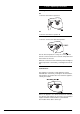
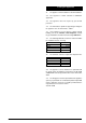
1. User’s Operating Instructions Switching on and off: On 1. Turn the main switch to position I. Off 1. Turn the main switch to position 0. Water temperature control: 1. Turn the control to the desired temperature. The hot water temperature is set by the control position. Turn the control clockwise to increase the temperature and anticlockwise to decrease. When the control is set at the maximum position the highest water temperature is achieved by controlling the flow at the tap.
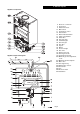
2. General Layout Appliance components Fig. 3 Appliance water flow diagram.
3. Technical Data The appliance and flue components are packed in separate cartons. The appliance is for use with Natural Gas only. The Installation notes in these Instructions, particularly those regarding Maximum Flue Lengths and Configuration Options, take precedence over any universal instructions included in flue component packs.
4. Dimensions and Fixings Fig.
5. General Information 6. Installation Regulations 5.1 GENERAL INSTALLATION If the appliance is to be fitted into a compartment, the compartment must conform to the requiremens of BS 6798. Do not place anything on top of the appliance. The clearances specified for servicing must be maintained. 6.1 Warning - Check the information on the data plate is compatible with local conditions. 5.2 SHOWERS If a shower control is supplied from the appliance it should be of the thermostatic or pressure balanced type.
7. Siting the Appliance 7.1 The appliance is NOT suitable for external installation. 7.2 The appliance is NOT suitable for SE DUCT application. 7.3 The appliance does not require any special wall protection. 7.4 The wall must be capable of supporting the weight of the appliance. See Technical Data – Table 1. 7.5 If the appliance is to be fitted in a timber framed building, refer to the Institute of Gas Engineers, ”Guide for gas installations in timber framed housing” IGE/UP/7. 7.
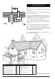
8. Siting the Flue Terminal See Fig. 7. 8.1 The flue must be installed as specified in BS 5440:Part 1. 8.2 The terminal must not cause an obstruction nor the discharge cause a nuisance. 8.3 If the terminal is fitted within 1000 mm of a plastic or painted gutter or within 500 mm of painted eaves then an aluminium shield at least 1000 mm long should be fitted to the underside of the gutter or painted surface. 8.
9. Air Supply 9.1 The appliance does not require a separate vent for combustion air. 9.2 The appliance may be installed in an unvented compartment. 9.3 There must be sufficient clearance around the appliance to allow proper circulation of air. The clearances required for operation will normally be adequate. 9.4 Refer to BS 6798 and BS5440:2 for additional information. 10. Gas Supply 10.1 The gas installation should be in accordance with BS 6891. 10.
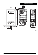
5 6 7 8 92 117 118 119 226 228 Temperature sensor Water flow sensor Fuse1,25A Fuse 2A Gas valve Ignition electrode Sensing electrode Temperature limit stat Fan Pressure switch Fig.
11. Electrical Fig. 9 See Fig. 8. 11.1 MAINS SUPPLY. 230 V ~, 50 Hz, 65 watts. 11.2 It must be possible to completely isolate the appliance. 11.3 The following connection alternatives must be used: A 3 amp fused three-pin plug and unswitched shuttered socket outlet (both complying with the requirements of BS 1363) or a double pole isolator with a contact separation of 3mm in all poles and supplying the appliance and controls only. 11.4 The appliance must be earthed. 11.5 Mains Cable. 0.75mm2 (24 x 0.
12.2 FLUE RESTRICTION The Installation notes in these Instructions, particularly those regarding Maximum Flue Lengths and Configuration Options, take precedence over any universal instructions included in flue component packs. To ensure the correct operation of the appliance, certain flue lengths require one of two flue restrictor rings to be fitted to the air inlet. (Fig. 12).
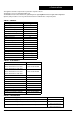
Horizontal configuration Configuration A Configuration B Configuration C Configuration D White flue elbow only – no additional bends White Flue Elbow + 1 x 90 degree bend White Flue Elbow + 2x 45 degree bends White Flue Elbow + 2x 90 degree bends Direct vertical rise from the Configuration appliance: Vertical Adapter E + 1 x 90 degree bend Minimum flue length: Rear flue, 230mm wall thickness. Flue length Restrictor 4.0 m Max 2.2 m Max 2.5 m Max 1.8 m Max 3.
12.4 FITTING A VERTICAL FLUE Possible configurations of flue are as per Fig. 17. Vertical flue kits and flue extension components are detailed in Section 3, Page 6, Table 2 - Flue Details. For vertical application the white painted elbow is discarded. The Maximum and Minimum flue lengths available for vertical configurations are as per table 9.
12.4.2 Extended Vertical Installation Example of flue measurement with one flue extension Example of flue measurement with two flue extensions Flashing kit Roof Vertical flue lengths may be extended to the limits as stated in Table 9 using standard 1m extension kits and 45 and 90 degree elbows. Secure the Flashing kit to the roof. Refer to Fig. 20.
13. Commissioning Before commissioning the appliance, the gas installation must be purged and tested for gas soundness in accordance with BS 6891. Fig. 22 1 2 3 4 18 Burner pressure measuring point Minimum gas flow ajustment screw Maximum gas flow adjuster Gas supply pressure measuring point 13.1) Ensure the gas isolation valve is turned off. 13.2) Remove the appliance outer case. 13.
14. Inspection and Servicing Warning Isolate electrical supply before servicing the appliance. For reasons of safety and economy it is recommend that the appliance is serviced annually. The servicing must be carried out by a competent person. Before commencing any service operation turn off the gas supply at the main gas isolation valve. Ensure that the appliance is cool. ACCESS FOR SERVICING Pull of the fascia and undo the two fixing screws. Lift the outer case clear. 14.
14.5 Service adjustment 14.5.1 Max and Min gas rate adjustment Do NOT use magnetic tools to adjust the gas valve. Always adjust the MAXI MU M rate BE FORE the MINIMUM. It is only necessary to adjust the minimum gas rate if the burner frequently goes out when the water flow is reduced toward the minimum specified. Fig. 25 - Max. adjustment position Set the main switch to position O (off).
14.5.3 Temperature range selection Appliance temperature range is set to 35°C - 60°C. Placing jumper JP7, temperature range changes to 38° 50°C. Fig.
15. Replacement of parts Warning: Isolate electrical supply before servicing the appliance. Any servicing or parts replacement must be carried out by a competent person. Use only genuine Manufacturer’s Parts. Before commencing servicing or parts replacement turn off the gas supply at the main gas isolation valve and ensure that the appliance is cool. 15.1 Main Burner Disconnect the spark electrode and the sensing electrode at the main burner.
as per Section 15.5.1. 15.6 Control Unit Unfasten the two screws securing the front panel of the control unit and remove. Disconnect inlet cable and all wiring connections. Remove control unit by depressing the two curved finger tabs on top of the box and withdraw forward. Replace the control unit and reconnect the wiring. Carry out Gas Type selection as in Section 15.5.2 and Performance Optimisation as Section 14. 15.7 Fuses Unfasten the two screws securing the front panel of the control unit and remove.
16. Fault Finding Note: Installation, maintenance and repairs must be carried out only by a competent person.
17. Short Parts List Item 6 720 607 160 Baxi Potterton Number Spark Electrode 5111115 Sensing Electrode 5111116 Flow Sensor 5111117 Control Unit 5111118 Fuse T 1.
18.
GENERAL ENQUIRIES (GB) 08706 060 780 TECHNICAL (GB) 08706 049 049 SERVICE (GB) 08706 096 096 LITERATURE REQUEST (GB) 08706 060 623 TECHNICAL (IE) 1850 560 570 Baxi Potterton A Trading Division of Baxi Heating U.K. Ltd Brownedge Road Bamber Bridge Preston Lancashire PR5 6SN www.baxipotterton.co.