
Operating instructions

10 6 720 607 160
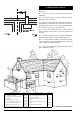
8. Siting the Flue Terminal
See Fig. 7.
8.1 The flue must be installed as specified in BS
5440:Part 1.
8.2 The terminal must not cause an obstruction nor the
discharge cause a nuisance.
8.3 If the terminal is fitted within 1000 mm of a plastic or
painted gutter or within 500 mm of painted eaves then an
aluminium shield at least 1000 mm long should be fitted to
the underside of the gutter or painted surface.
8.4 If a terminal is fitted less than 2 metres above a
surface to which persons have access then a guard must
be fitted.
8.5 The terminal guard must be evenly spaced about the
flue terminal and fixed to the wall using plated screws.
8.6 In certain weather conditions a terminal may plume
when the appliance is operated. Siting where this could
cause a nuisance should be avoided.
8.7 Take care to ensure that combustion products do not
enter ventilated roof voids.
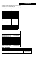
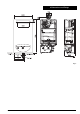
Fig. 7 - Siting of the flue terminal
Fig. 6
TERMINAL POSITION MIN. DIST
.
A -
directly below an openable window or
other opening e.g. air brick.
300 mm
B - Below gutters, soils pipes or drain pipes.
75 mm
C - Below eaves.
200 mm
D - Below balconies or car port roof.
200 mm
E - From vertical drain pipes and soil pipes.
150 mm
F - From internal or external corners.
300 mm
G - Above ground, roof or balcony level.
300 mm
H - From a surface facing a terminal.
600 mm
TERMINAL POSITION MIN. DIS
.
I - From a terminal facing a terminal.
1200 mm
J -
From an opening in a car port (e.g. door
window) into dwelling.
1200 mm
K -
Vertically from a terminal on the same
wall.
1500 mm
L -
Horizontally from a terminal on the same
wall.
300 mm
M - From door, window or air vent 300 mm