
Operating instructions

56 720 607 160
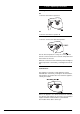
2. General Layout
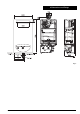
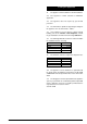
Fig. 3
Appliance water flow diagram.
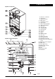
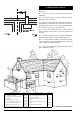
Fig. 4
Appliance components
4 Electronic control box
5 Heat sensor
6 Water flow sensor
10 Main switch
11 Temperature control
12 Reset button
13 Burner Indicator Button
17 Safety solenoid EV1
25 Water filter
28 Hot water pipe
29 Cold water pipe
35 Gas inlet pipe
42 Gas filter
49 Injector
50 Burner
55 Heat exchanger
92 Gas valve
117 Ignition electrode
118 Sensing electrode
119 Temperature limit stat
200 Minimum gas flow adjustment
screw
201 Maximum gas flow adjuster
210 Main valve
221 Flue support ring
222 Exhaust gas collector
224 Flow sensor
226 Fan
228 Pressure switch
229 Sealed box