
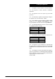
Operating instructions

6 6 720 607 160
3. Technical Data
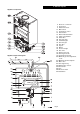
The appliance and flue components are packed in separate cartons.
The appliance is for use with Natural Gas only.
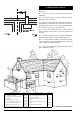
The Installation notes in these Instructions, particularly those regarding Maximum Flue Lengths and Configuration
Options, take precedence over any universal instructions included in flue component packs.
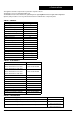
TABLE 1 - GENERAL
TABLE 3 - PERFORMANCE
TABLE 2 - FLUE DETAILS
Natural Gas
Gas category
I
2H
Appliance Type
C
12
, C
32
Minimum rated output 10 kW
Maximum rated output 23.8 kW
Rated input (Net) 27 kW
Gas rate (CV 34 MJ/m
3
)2.9 m
3
/hr
Inlet pressure 20 mbar
Number of injectors 14
Injector diameter 1.20 mm
Injector marking 120
Burner pressure (max) 12.7 mbar
Burner pressure (min) 2.5 mbar
Height 700 mm
Width 388 mm
Depth 220 mm
Dry weight 20 kg
Gas connection 15mm Copper
Hot/cold water connections 15mm Copper
Electrical protection IPX4D
Wall hole size 110 mm Diameter
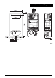
Standard Horizontal Flue Kit
490mm wall thickness rear outlet Sales Code 430183
400mm wall thickness side outlet
Horizontal Flue Kit
680mm wall thickness rear outlet Sales Code 430184
590mm wall thickness side outlet
Flue Extension 1m Sales Code B4286
90° Bend Kit Sales Code 31/19034
135° Bend Kit Sales Code 31/19035
Telescopic Flue In Line Elbow Adaptor Sales Code 430174
Vertical Adaptor Sales Code 238014
Concentric Vertical Flue Kit Sales Code 238015
Flat roof flashing kit Sales Code 31/19040
Pitched roof flashing kit Sales Code 31/19041
Wall liner / internal flue fixing kit Sales Code 238012
Terminal guard Sales Code 205792
Maximum cold water supply inlet pressure 12 bar
Minimum cold water supply inlet pressure to operate the appliance 0.3 bar
Domestic hot water delivery with temperature control knob fully anticlockwise 4 to 14 litres/minute at
25°C tem
p
erature rise
Domestic hot water delivery with temperature control knob fully clockwise 3 to 6 litres/minute at
55°C tem
p
erature rise