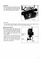
/2" MODEL 3612B INSTRUCTION MANUAL DOUBLE INSULATION Collet chuck capacity Main body stroke No load speed Overall length Net weight 112" 0 65 mm (0 - 2-9/16") 23,000 R/min. 287 m m (1 1-5/16") 5 7 kg (12.
IMPORTANT SAFETY INSTRUCTIONS (For All Tools) WARNING: WHEN USING ELECTRIC TOOLS, BASIC SAFETY PRECAUTIONS SHOULD ALWAYS BE FOLLOWED TO REDUCE THE RISK OF FIRE, ELECTRIC SHOCK, AND PERSONAL INJURY, INCLUDING THE FOLLOWING: READ ALL INSTRUCTIONS. 1. KEEP WORK AREA CLEAN. Cluttered areas and benches invite injuries. 2. CONSIDER WORK AREA ENVIRONMENT. Don't use power tools in damp or wet locations. Keep work area well lit. Don't expose power tools t o rain.
13. DISCONNECT TOOLS. When not in use, before servicing, and when changing accessories, such as blades, bits, cutters. 14. REMOVE ADJUSTING KEYS AND WRENCHES. Form habit of checking t o see that keys and adjusting wrenches are removed from tool before turning it on. 15. AVOID UNINTENTIONAL STARTING. Don't carry plugged-in tool with finger on switch. Be sure switch is OFF when plugging in. 16. OUTDOOR USE EXTENSION CORDS.
ADDITIONAL SAFETY RULES 1. These bits come fully sharpened. Handle them carefully t o prevent injury. 2. Check the bit carefully for cracks or damage before operation. Replace cracked or damaged bit immediately. 3. Avoid cutting nails. Inspect for and remove all nails from the workpiece before operation. 4. Make sure the shaft lock is released before the switch is turned on. 5. Hold the tool firmly with both hands. 6. Keep hands away from rotating parts. 7.
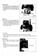
Installing bit Loosen the collet nut and insert the bit into the chuck hole. Press the shaft lock and use the wrench to secure the bit carefully. Use the collet sleeve if necessary. 0 I CAUTION : 0 Do not tighten the collet chuck without inserting a bit; do not install a small bit without using a collet sleeve. Either can lead t o collet chuck breakage. Adjusting cutting depth Release the lock lever and lower the tool to the desired depth. Then pull up on the lock lever to lock.
Stopper block .The stopper block has an adjustment hex bolts which move 1 mm (1/32")per turn. After obtaining the desired depth setting, tighten the hex nut on the bolt with the spanner. I \ block Nylon nut By turning the nylon nut, the upper limit of the tool can be adjusted. When the tip of the bit i s retracted more than required in relation to the base plate surface, turn the nylon nut to lower the upper limit for more effective routing.
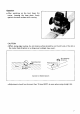
Operation *After switching on the tool, lower the router, keeping the base plate firmly against the work surface while routing. CAUTION 0 When doing edge routing, the workpiece surface should be on the left side of the bit in the router feed direction or a dangerous kickback may result. (3 Bit revolving direction Correct bit feed direction 0 Adjustment should not be more than 15 mm (5/8")a t once when using straight bit.
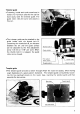
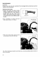
Straight guide .The straight guide is effectively used for straight cuts when chamfering or grooving. When grooving, the router tends to pull away to the left in relation to the feed direction. Install the straight guide on the right side to assure a good finished cut. .The straight guide with the guide holder installs on the router by means of the thumb bolts A. To obtain the desired distance between the bit and the straight guide, turn the fine adjustment screw (1.5" or 1/16" per turn).
Trimmer guide .Trimming, inside work and curved cuts in veneers for furniture and the like can be done easily with the trimmer guide. The guide roller rides the curve and assures a fine cut. *The trimmer guide can be attached to the guide holder with the thumb bolt B. Loosening the thumb bolt B, the distance between the bit and the guide surface can be adjusted by the fine adjustment screw (1.5 mm or 1/16" per turn). When the thumb bolt C is released, the guide roller can be moved.
MAINTENANCE CAUTION : Always be sure that the tool is switched off and unplugged before attempting to perform inspection and maintenance. Replacing carbon brushes 0 Remove and check the carbon brushes regularly. Replace when they wear down to about 6 mm (1/4") or less. Keep the brushes clean and free to slip in the holders. Both brushes should be changed a t the same time. Use only Makita carbon brushes. 0 Use a screwdriver to remove the brush holder cap as shown on the figure.
ACCESSORIES CAUTION : These accessories or attachments are recommended for use with your Makita tool specified in this manual. The use of any other accessories or attachments might present a risk of injury to persons. The accessories or attachments should be used only in the proper and intended manner. Templet guide Used for finishing a large quantity of articles of complicated shapes with the use of a templet. !mml Part NO.
Bits STRAIGHT -Single Flute CARBIDE TIPPED I PARTNO. A B C 0 E 733002-0A 733002-4A 3/8 1/2 1 1-1/4 1-1/2 1-3/8 1/2 112 2-3/4 2-7/8 HIGH SPEED STEEL STRAIGHT PART NO. A B C 0 E 733232-6A 118 5/16 Vl/8 1/4 1.518 - 2 Flute CARBIDE TIPPED PART NO. A B C D 733003-2A 733003-4A 733003-8A 3/16 1/4 5/16 7/16 3/4 1 1-3/8 1-3/16 1-1/8 1/4 114 114 E 2 2-1/ 8 2-3/16 HIGH SPEED STEEL (STRAIGHT - 2 Flute) STRAIGHT PART NO.
VEINING -Single Flute SOLID CARBIDE PART NO A B C D E 733007-8A 3/16 7/32 1-114 114 1-112 ROUND NOSE CARBIDE TIPPED & PART NO A 8 C D E 733008-2A 733008-4A 7330086A 733008-8A 733009-0A 114 318 112 15/32 9116 11116 11116 13116 1-114 1-114 1-114 1-114 1-114 114 114 114 114 114 1-718 2 2-3116 2.114 2-318 518 314 CORE BOX 4D c-- -J HIGH SPEED STEEL PART NO. A B C D E 733238-2A 114 114 1.3116 114 1-112 I I VEE GROOVING CARBIDE TIPPED PART NO.
" DOVE TAIL CARBIDE TIPPED PART NO. A B C D E 733009-6A 1I2 112 1-1/4 114 1-718 HIGH SPEED STEEL PART NO. A B C D E 733239-6A 112 112 1-318 114 2 STAGGER TOOTH -ID!- CARBIDE TIPPED PART NO. A B C D E 733007-0A 318 1-112 1-1I 4 112 3 PART NO. A B C D E 733030-4A 733030-6A 318 112 1 1 118 1 1-1/2 318 112 2-1/2 3-114 PANEL PILOT CARBIDE TIPPED HIGH SPEED STEEL CORNER ROUNDING PART NO.
BEADING CARBIDE TIPPED - Ball Bearing Pilot COVE PART NO. A B C D E 733121-4A 7331 21 -6A 7331 21-8A 733122-0A 7331 2 2 - 2 A 3116 114 5116 318 112 318 112 112 518 314 1-114 1-114 1-114 1-114 1-114 114 114 114 114 114 1.15116 CARBIDE TIPPED i ~ 2 2.1116 2-118 2-114 Ball Bearing Pilot PART NO A B C D E 733122-6A 733122-8A 733123-0A 114 318 112 318 112 518 1 1 1 114 114 114 1-518 1-314 1.718 REPLACEMENT BEARING - NO 733132-2A HIGH SPEED STEEL -Solid Pilot PART NO.
ROMAN OGEE CARBIDE TIPPED - Ball Bearing Pilot PART NO. A B C D E 7331 23-2A 733123-4A 5/32 1I 4 15/32 21/32 1.114 1-114 1/4 1I4 2 REPLACEMENT BEARING 2.118 - NO. 733132-2A FLUSH TRIMMER -Self Piloting SOLID CARBIDE 7’ BEVEL TRIMMER PART NO. A B C D E 733128-0A 1/4 1/4 1-1/16 114 1-9/16 - Self-Piloting SOLID CARBIDE PART NO. A B C D E 7331 28-2A 3/16 1I 4 1-1/16 114 1-9/16 PARTNO.
COMBINATION FLUSH122" BEVEL TRIMMER CARBIDE TIPPED PART NO. A B C D E 7331 28-6A 7116 112 1-114 114 1-314 ~~ 3 FLUTE FLUSH TRIMMER ASSEMBLY -Self Piloting SOLID CARBIDE CUTTER PART NO. A 8 C D E 733129-2A 518 318 1-114 114 2-318 REPLACEMENT BEARING - NO. 733132-6A 3 FLUTE 22" BEVEL TRIMMER ASSEMBLY -Self Piloting SOLID C RBlDE CUTTER PART NO. A B C 0 E 7331 29-4A 518 3/8 1-114 114 2-318 REPLACEMENT BEARING - NO.
3 FLUTE 22" BEVEL REPLACEMENT CUTTER L A t SOLID CARBIDE I PARTNO. A 733129-8A 318 8 C FOR BEVEL TRIMMER 1/4"REPLACEMENT ARBOR PART NO. A B C D E 733131-2A 1/4 318 1-114 1I 4 2.318 FOR FLUSH TRIMMER ASSEMBLY NO. 733129-2A AND NO. 733129-4A BALL BEARING PILOT 18 PART NO. A B 733132-2A 733132-4A 733132-6A 318 O.D. 1/2 O D . 5/8 O.D. 118 I.D. 3/16 I.D. 1/4 ID.
Jan - 2 4 -'E6 EN 12 mm (1/2") ROUTER Model 3612B 19
Jan MODEL 36128 ‘EMAiD $& DESCRIPTION MACHINE 24 86 EN DESCRIPTION MACHINE ~ ~ 1 1 1 1 1 4 1 2 3 4 5 6 2 7 8 9 10 11 12 13 14 15 16 17 18 19 4 1 1 1 1 1 4 1 1 2 1 1 1 1 1 1 1 1 1 1 1 1 1 20 21 22 23 24 25 26 27 28 29 30 31 32 - 1 1 - Nut M 1 0 Nylon Nut M 1 0 M O ~ Onourlng ~ Name Plate Rivet 0 5 FIELD ASSEMBLY Hex Bolt M5xB5 [With Washer] Countersunk Head Screw M4x14 [With Washer] Ball Bearing 201 2LLB Knob L Motor Bracket Compression Spring 10 Half Nut Pan Head Screw M5x40 [With