
User manual

IMPORTANT SAFETY PRECAUTIONS
! Before operating any router read and
understand all safety instructions in the
owner’s manual that came with the router.
! If you do not have a manual, contact the
manufacturer and obtain one before using
any power tool.
! Always wear eye protection in compliance
with ANSI safety standards when operating
any power tool.
! Always use proper guards and safety
devices when operating power tools and
machinery.
! Carefully check router bits before each use.
Do not use if damage or defect is
suspected.
! Do not exceed the recommended RPM for
any router bit.
! Do not wear loose clothing or jewelry that
may catch on tools or equipment.
! Unplug the tool or machine when mounting
or making any adjustments to mechanical
performance.
DO NOT USE A CORDLESS DRILL TO
RAISE AND LOWER THE LIFT CARRIAGE.
THE AMOUNT OF FRICTION WILL CAUSE
PREMATURE WEAR OF THE THREADS
AND WILL VOID THE WARRANTY
ROUTER SAFETY PRECAUTIONS
! Never force the bit or overload the router
beyond the expectations of the tool.
! Be sure that at least 3/4 of the shank
length is inserted securely in the router
collet.
! Never bottom out the bit in the collet. Allow
1/8” clearance between shank and bottom
of collet.
! Always make sure the fence on your router
table is locked into position before each
use.
! Always rout in two or more passes when
large amounts of stock must be removed.
! Use reduced RPM speeds for large
diameter bits.
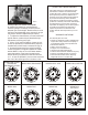
MOUNTING THE ROUTER
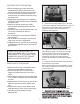
1. Remove the carriage plate (Fig. 1). Using the
5/32 hex key supplied, remove the four 1/4-20 x 1”
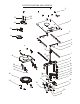
flat head cap screws (Item #16 from the parts
diagram on pages 7 & 8) and remove the
aluminum carriage plate.
2
FIG. 1
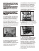
2. Remove the master ring (Item# 26 on the
parts drawing - pages 7 & 8) from the carriage
plate. Using the 5/32 hex wrench supplied,
remove the six 1/4-20 x 3/4” flat head cap
screws (Fig. # 2) that secure the clamping
brackets (item #25) to the aluminum carriage
plate.
3. Remove the sub-base and screws that attach
the sub base to your router.
Note: If your sub-base is not removeable, remove
the screws that will be used to attach your router
to the master ring.
FIG. 2
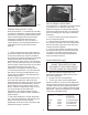
FIG. 3
ATTACH THE ROUTER TO THE MASTER RING
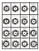
1. On page 5 & 6 of the manual there are
drawings showing the mounting hole patterns for
different routers. Locate your router and then
determine which holes to use for mounting your
router to the master ring.
On page 5 & 6 of the manual there are
drawings showing the mounting hole patterns for
different routers. Locate your router and then
determine which holes to use for mounting your
router to the master ring.