
User manual

ATTACH ROUTER TO THE MASTER RING (Cont’d)
Using a felt tip marker or a pencil make a mark
on the mounting plate for each hole that you will
be using for your router.
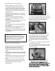
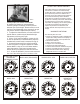
With the holes marked on the master ring, place
the mounting plate on the base of your router
and rotate it to line up the tapped holes in your
router (Fig. 3). The countersunk holes and the
engraving on the master ring should be facing
upwards and with the engraved “T” to the top and
the engraved “B” to the bottom. Don’t worry
about handle location at this point as the master
ring can be rotated to any position after the
mounting plate is re-attached to the aluminum
carriage plate.
Note: The master ring is 1/4” thick and the
screws that come with your router may not be
long enough to secure your router safely. If this is
the case source longer flat head screws from a
local hardware or automotive parts supplier.
When fastening your router to the master plate,
lightly secure the screws at first to ensure that
the master ring will locate properly in the center
of your router and then tighten all screws
securely. Also, with some routers the screws used
to attach the sub-base may not be the best
solution for mounting your router to the mounting
ring. Look for 3 or more larger diameter tapped
holes and obtain the proper size screws for the
safest mounting solution.
Using a felt tip marker or a pencil make a mark
on the mounting plate for each hole that you will
be using for your router.
With the holes marked on the master ring, place
the mounting plate on the base of your router
and rotate it to line up the tapped holes in your
router (Fig. 3).
Don’t worry
about handle location at this point as the master
ring can be rotated to any position after the
mounting plate is re-attached to the aluminum
carriage plate.
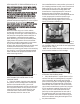
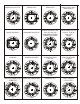
Once satisfied with the router position, place one of
the clamping brackets into the correct location and
feed one of the 1/4-20 x 3/4” flat head screws
from under the aluminum carriage plate and
thread into the clamping bracket for a loose fit.
Repeat this step for the other five clamping
brackets. Ensure that all the mounting brackets are
in their proper position and the master ring is
securely sitting into the recessed hole in the
carriage plate. Securely tighten all six of the 1/4-
20 x 3/4” bracket screws (Fig. 4).
3
FIG. 4
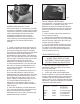
2. Using the 1/4-20 x 1” flat head screws (Item#
16, removed in step 1), re-install the carriage plate to
the Rout-R-Lift™ (Fig. 5)
. NOTE: Use the socket head cap screws as locating
pins for easier installation of the carriage.
FIG. 5
RE-ATTACHING THE MASTER RING TO THE
CARRIAGE PLATE
1. Place the master ring with router attached
into position on the carriage plate. Consider the
position of the handle location, your on/off
switch and variable speed controls to ensure they
are in the best location for easy access once the
router lift is put into your router table. You can
rotate the router at this time to achieve your
most desired position for ease of use.
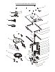
ATTACHING THE LEVELING BARS
1. Place the Rout-R-Lift™ upside down on a flat
surface. Take the four leveling bars (2 long and 2
short - items #3 & #6 from the parts list) and
position them along the corresponding edges of
the underside of the top plate (Fig. 6). Each bar
attaches with two of the 6-32 x 5/16” flat head
cap screws (item #4 from the parts list) using the
5/64” hex wrench supplied. Insert each of the
(10) 1/4-28 x 1/4” set screws (item #5 from
parts list) into the tapped holes at each end of
the leveling bars and one in the center of each
long bar. Thread the set screws in until they just
bottom out without raising the leveling bar from
the plate underneath.
FIG. 6