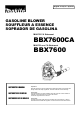
English / Français / Spanish GASOLINE BLOWER SOUFFLEUR A ESSENCE SOPRADOR DE GASOLINA MAKITA CA Statement BBX7600CA MAKITA non CA Statement BBX7600 INSTRUCTION MANUAL Important: Read this instruction manual carefully before putting the Blower into operation and strictly observe the safety regulations! Preserve instruction manual carefully! INSTRUCTIONS D’EMPLOI Importante: Lisez attentivement ce manuel utilisateur avant de mettre en route le souffleur et respectez scrupuleusement les consignes de séc
English Table of Contents Thank you very much for selecting the MAKITA blower. We are pleased to be able to offer you the MAKITA blower, which is the result of a long development program and many years of knowledge and experience. Page Symbols ........................................................................................ 2 Safety instructions ................................................................... 3-5 Technical data ....................................................................
SAFETY INSTRUCTIONS General Instructions • To ensure correct and safe operation, the user must read, understand and follow this instruction manual to assure familiarity with the handling of the blower (1). Users insufficiently informed will risk danger to themselves as well as others due to improper handling. • It is recommended only to loan the blower to people who have proven to be experienced with blowers. • Always hand over the instruction manual.
Start the Blower only in accordance with the instructions. Do not use any other methods for starting the engine (6)! • Use the blower and the tools supplied only for applications specified. • Start the blower engine only after the entire tool has been assembled. Operation of the tool is permitted only after all the appropriate accessories are attached. • The engine is to be switched off immediately if there are any engine problems.
Method of operation • Use the blower only in good light and visibility. During cold seasons beware of slippery or wet areas, ice and snow (risk of slipping). Always ensure a safe footing. • Never work on unstable surfaces or sleep terrain. • To reduce the risk of personal injury, do not direct air blast towards bystanders, since the high pressure of the air flow could injure eyes and could blow small objects at great speed.
TECHNICAL DATA BBX7600 BBX7600CA Model Mass (without blower pipe) Dimension (without blower pipe L x W x H) (kg) (mm) 350 × 430 × 495㧔13.716.919.5 in㧕 -1 Max. engine speed (min ) Idling speed (min ) Engine displacement 10.2㧔22.4lbs㧕 7,200 -1 2,800 (mL) 75.6㧔4.61 cu,in㧕 Fuel Fuel tank capacity Automobile gasoline (L) SAE 10W-30 oil of API Classification, Class SF or higher (4-stroke engine for automobile) Engine oil Engine oil volume 1.9㧔64.2 fl.oz㧕 (L) 0.22㧔7.4 fl.
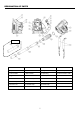
DESIGNATION OF PARTS OPTION DESIGNATION OF PARTS DESIGNATION OF PARTS DESIGNATION OF PARTS DESIGNATION OF PARTS 1. Stop switch 8. Choke Lever 15. Plug Cover 22. Blower Pipe 2. Control Handle 9. Starter Handle 16. Spark Plug 23. Blower Nozzle L=200 3. Trigger Lever 10. Fuel Tank 17. Oil Cap 24. Hose Band Ǿ100 4. Cruise Control Lever 11. Fuel Tank Cap 18. Oil Drain Bolt 25. Hose Band Ǿ76 5. Primer Pump 12. Muffler 19. Elbow 26. Blower Nozzle L=450 6. Element Cover 13.
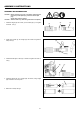
ASSEMBLY INSTRUCTIONS ASSEMBLY OF BLOWER PIPES CAUTION : Before performing any work on the blower, always stop the engine and pull the spark plug connectors off the spark plug. Always wear protective gloves! CAUTION : Start the blower only after having assembled it completely. 1. Assemble straight pipe with swivel (3) into flexible pipe (1) and tighten hose band 㱢76 (2). 2. Install control handle (4) onto straight pipe with swivel and tighten the clamp screw (5). (2) (1) (3) (4) (5) 3.
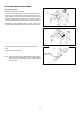
ATTACHING THE SHOULDER STRAP Attachment Procedure Attaching the shoulder strap to the blower. • Loop the end of the strap through the lower part of the hanger as shown in the figure at right. The side of the strap that has the folded tip should be facing outwards. Then, bring the end of the strap back over the hanger and thread the remaining length of the strap through the buckle (1).
BEFORE STARTING THE ENGINE 1. Checking and Refilling Engine Oil 1) Follow the procedure below when the engine oil is cold i.e. the blower has not been running. 䊶Inspection: Set the blower down on a level surface and remove the oil cap. Verify that the oil level is within the upper and lower limit marks on the oil level gauge. If the oil is not up to the 100mL level, fill up with new oil. 䊶Adding Oil: Set the blower down on a level surface and remove the oil cap.
2. Fuel supply WARNING • When supplying the fuel, be sure to observe the following instructions to prevent ignition or fire: − − − − − Fuel supply must be made in a place free of fire. Never bring the fire (smoking, etc.) near to the place of fuel supply. Stop the engine and allow the engine to cool down before fuel supply. Open the fuel tank cap full of fuel slowly. The fuel may sprout out under internal pressure. Take care not to spill the fuel. Any spilled fuel must be wiped clean.
OPERATION 1. Starting WARNING • Never attempt engine start in a place where the fuel has been supplied. When starting the engine, keep a distance of at least 3 m. − Otherwise, it will may cause ignition or fire. • Exhaust gas from the engine has toxic consequences. Do not operate the engine in a poorly-ventilated place, such as in a tunnel, building, etc. − Operating the engine in the poorly-ventilated place may cause poisoning by exhaust gas.
NOTE • The engine may be damaged if the choke lever is moved further beyond the “CLOSE” position. • If the engine stops with an explosion sound or if the engine started, but stopped before operation of the choke lever, return this lever to the “OPEN” position and pull the starter handle several times to start the engine again.
OPERATION METHOD 1. Adjusting Shoulder strap To tighten straps To loosen straps Adjust the shoulder strap to a length that is comfortable to work while carrying the blower. Adjust as shown in the figure. 2. Adjusting the control lever Move the control handle along the swivel pipe to the most comfortable position. 3. Blower operation While operating the blower, adjust the throttle bar so that the wind force is appropriate for the work location and conditions.
INSPECTION AND MAINTENANCE! ! DANGER • Before inspection and maintenance, stop the engine and allow it to cool. Remove also the spark plug and plug cap. − If inspection or maintenance is attempted immediately after engine stop or with the plug cap left attached, the operator may suffer burn or an accident due to careless startup. • After inspection and maintenance, be sure to confirm that all parts are assembled. Then, proceed to operation. 㩷 1.
2. Cleaning of air cleaner Knob bolt WARNING 㧦INFLAMMABLES STRICTLY PROHIBITED Element cover Interval of Cleaning and Inspection: Daily (every 10 operating hours) (1) Loosen the knob bolt. (2) Remove the air cleaner cover. (3) Take out the element and remove any dirt with the brush. Note: The element is a dry type and should not get wet. Never wash with water. (4) Replace the element with a new one if it is damaged or very dirty. Part No.
4. Cleaning the fuel filter • Clogged fuel filter may cause difficulty of start-up or failure of engine speed increase. • Check the fuel filter regularly as follows: (1) Remove the fuel tank cap, drain the fuel to empty the tank. Check the tank inside for any foreign materials. If any, wipe clean such materials. (2) Pull out the fuel filter with wire through the oil filling port. (3) If the fuel filter surface is contaminated, clean it with gasoline.
Fault location Fault System Observation Cause Engine not starting or with difficulty Ignition system Ignition spark O.K. Fault in fuel supply or compression system, mechanical defect No ignition spark STOP-switch operated, wiring fault or short circuit, spark plug or connector defective, ignition module faulty Fuel supply Fuel tank filled Incorrect choke position, carburetor defective, fuel supply line bent or blocked, fuel dirty.
TROUBLESHOOTING Before making a request for repairs, check a trouble for yourself. If any abnormality is found, control your machine according to the description of this manual. Never tamper or dismount any part contrary to the description. For repairs, contact Authorized Service Agent or local dealership. State of abnormality Probable cause (malfunction) Failure to operate primer pump Engine does not stop. Push 7 to 10 times. Low pulling speed of starter rope Pull strongly. Lack of fuel Feed fuel.
MAKITA LIMITED ONE YEAR WARRANTY Warranty Policy Every Makita tool is thoroughly inspected and tested defects from workmanship and materials for the period of any trouble develop during this one year period, return Factory or Authorized Service Centers. If inspection material, Makita will repair (or at our option, replace) before leaving the factory. It is warranted to be free of ONE YEAR from the date of original purchase.
EMISSION COMPLIANCE PERIOD For handheld engines : The Emissions Compliance Period referred to on the Emissions Compliance label indicates the number of operating hours for which the engine has been shown to meet Federal emission requirements. Category C=50 hours, B=125 hours, and A=300 hours. Air Index and durability period information The Air Index Information hang-tag for this engine is provided in accordance with the California emission regulations.
FEDERAL EMISSION COMPONENT DEFECT WARRANTY EMISSION COMPONENT DEFECT WARRANTY COVERAGE - This emission warranty is applicable in all States, except the State of California Makita U.S.A., Inc., (herein "Makita") warrant to the initial retail purchaser and each subsequent owner, that this utility equipment engine (herein "engine") was designed, built, and equipped to conform at the time of initial sale to all applicable regulations of the U.S.
OBTAINING WARRANTY SERVICE To obtain warranty service, take your engine to the nearest MAKITA Factory Service Center authorized by MAKITA. Bring your sales receipts indicating date of purchase for this engine. The dealer or service center authorized by Makita will perform the necessary repairs or adjustments within a reasonable amount of time and furnish you with a copy of the repair order. All parts and accessories replaced under this warranty become the property of Makita.
THINGS YOU SHOULD KNOW ABOUT THE EMISSION CONTROL SYSTEM WARRANTY MAINTENANCE AND REPAIRS You are responsible for the proper use and maintenance of the engine. You should keep all receipts and maintenance records covering the performance of regular maintenance in the event questions arise. These receipts and maintenance records should be transferred to each subsequent owner of the engine. Makita reserves the rights to deny warranty coverage if the engine has not been properly maintained.
CALIFORNIA EMISSIONS CONTROL WARRANTY STATEMENT YOUR WARRANTY RIGHTS AND OBLIGATIONS The California Air Resources Board and Makita USA, Inc are pleased to explain the emissions control system’s warranty on your 2007 and later small off-road engine. In California, new equipment that use small off-engines must be designed, built, and equipped to meet the State’s stringent anti-smog standards.
(1) Any warranted part that is not scheduled for replacement as required maintenance in the written instructions required by subsection (d) must be warranted for the warranty period defined in Subsection (b)(2). If any such part fails during the period of warranty coverage, it must be repaired or replaced by the manufacturer according to Subsection (4) below. Any such part repaired or replaced under the warranty must be warranted for the remaining warranty period.
(3) Ignition System (i) Spark Plugs. (ii) Magneto or electronic ignition system. (iii) Spark advance/retard system. (4) Miscellaneous Items Used in Above Systems (i) Hoses, Sealing gaskets, belts, connectors, and assemblies. Makita USA, Inc will furnish with each new engine written instructions for the maintenance and use of the engine by the owner.
Frençais Vous venez d’acheter un souffleur MAKITA, fruit d’importants programmes de développement et de nombreuses années d'études et d’expérience et nous vous en remercions. Table des Matières Page Symboles .................................................................................... 28 Consignes de sécurité .......................................................... 29-30 Caractéristiques techniques ........................................................ 32 Liste des pièces ......................
CONSIGNES DE SECURITE Généralités • Pour tirer le meilleur parti de votre machine, vous devez lire, assimiler et respecter les instructions figurant dans ce manuel (1). Les utilisateurs mal informés risquent, par des manipulations inappropriées, de se blesser ou de blesser leur entourage. • Il est conseillé de ne prêter cet appareil qu’aux personnes ayant déjà une certaine expérience des souffleurs. • Dans ce cas, leur confier aussi le manuel d’instruction.
Avant de mettre la machine en marche, assurez-vous que toutes les instructions sont bien respectées. N’utilisez pas d’autres méthodes de mise en marche de l'appareil (6). • N’utilisez la machine et les outils fournis que pour les applications spécifiées. • Ne mettez la machine en marche que lorsque tous les accessoires ont été mis en place. L’appareil ne fonctionne que lorsque tous les accessoires appropriés y sont fixés. • En cas de problème, arrêtez immédiatement l’appareil.
Fonctionnement • N’utilisez l’appareil que dans des endroits bien éclairés, où la visibilité est bonne. • Pendant les saisons fraiches, évitez les sols glissants ou humides, la glace et la neige. Ayez toujours une position stable. • N’utilisez jamais l’appareil sur des sols meubles ou en pente. • Pour éviter tout risque de blessure, ne dirigez jamais l’évacuation d’air vers les personnes pouvant se trouver à proximité pour éviter toute projection.
CARACTÉRISTIQUES TECHNIQUES BBX7600 BBX7600CA Modèle Poids (sans les tubes) Dimensions (sans les tubes) (L x l x H totales) Vitesse maxi du moteur Vitesse au ralenti Cylindrée totale du moteur (kg) 10.2 (mm) 350 × 430 × 495 -1 (min ) 7,200 -1 (min ) 2,800 (mL) 75.6 Carburant Volume du reservoir à carburant Essence à automobile (L) 1.9 SAE 10W- 30 huile de la classification API, classe SF ou supérieure (moteur à quatre temps pour automobile) Huile pour moteur Volume d'huile à moteur (L) 0.
LISTE DES PIÈCES Optionnel Désignation des pièces Désignation des pièces Désignation des pièces Désignation des pièces 1. Interrupteur d’arrêt 8. Levier d’étrangleur 15. Capot de bougie 22. Tube de souffleur 2. Poignée de contrôle 9. Poignée de démarrage 16. Bougie 23. Gicleur de souffleur L=200 3. Déclencheur 10. Réservoir à carburant 17. Bouchon à huile 24. Collier de serrage φ 100 4. Lever du Régulateur de vitesse 11. Bouchon du réservoir à carburant 18. Boulon de vidange d’huile 25.
INSTRUCTIONS DE MONTAGE Montage du tube de soufflante ATTENTION : Avant toute opération sur le souffleur, coupez toujours le moteur et débrancher les connecteurs de bougie. Portez toujours des gants de protection! ATTENTION: Ne mettre le souffleur en marche que lorsqu’il est complètement monté. 1. Assembler le tuyau droit pour le raccorder avec la cheville au flexible et serrer le tuyau de soufflerie diamètre φ76 (2). 2.
Fixation de la bandoulière Procédure de fixation Fixation de la bandoulière au souffleur. • Passez le bout de la bandoulière dans la fente de suspension en le passant par le bas tel qu'indiqué dans la figure à droite. Le côté de la bandoulière avec le bout plié doit être tourné vers l'extérieur. Amenez, ensuite, le bout de la bandoulière par dessus la fente de suspension et enfilez la longueur restante dans la boucle (1).
AVANT DE DÉMARRER LE MOTEUR 1. Vérification et remplissage de l’huile 1) Suivre la procédure ci-dessous lorsque l’huile moteur est froide, par exemple lorsque le souffleur n’a pas été utilisé. 䊶Vérification: Placer le souffleur par terre sur une surface plane et retirer le bouchon à huile. Vérifier que le niveau d’huile se trouve entre les deux repères de niveau supérieur et inférieur sur l’indicateur du niveau d’huile.
2. Alimentation en carburant AVERTISSEMENT • Lors de l’alimentation en carburant, s’assurer que les instructions suivantes sont respectées pour éviter l’inflammation ou l’incendie: − L’alimentaion en carburant doit être effectuée à l’endroit où il n’y a pas de feu. Ne jamais apporter du feu (tabac, etc.) près de l’endroit de l’alimentaion en carburant. − Arrêter le moteur et laisser refroidir le moteur avant d’alimenter du carburant. − Ouvrir lentement le bouchon du réservoir à carburant.
FONCTIONNEMENT 1. Mise en marche AVERTISSEMENT • Ne jamais tenter de démarrer le moteur dans l’endroit où le carburant a été alimenté. Le démarrage du moteur doit s’effectuer en maintenant une distance de 3 m au moins. − Sinon, l’inflammation ou l’incendie peut se provoquer. • Le gaz d’échappement du moteur comporte de substances toxiques. Ne pas mettre le moteur en marche dans l’endroit faiblement ventilé, tel que dans le tunnel, le bâtiment, etc.
NOTE • Le moteur pourra être endommagé si le levier d’étrangleur est déplacé au-delà de la position “CLOSE”. • Si le moteur s’arrête avec un bruit d’explosion ou si le moteur a démarré, mais s’est arrêté avant la manoeuvre de le levier d’étrangleur, remettre ce levier à la position “OPEN” et tirer la poignée de démarreur à quelques fois pour démarrer encore le moteur.
MODE OPERATOIRE 1. Réglage de la bandoulière Pour serrer les bandoulières Pour déserrer les bandoulières Réglez les bandoulières à la longueur adéquate vous permettant de porter le souffleur confortablement pour travailler. Réglez les bandoulières tel qu’indiqué sur la figure. 2. Réglage du levier du régulateur Déplacez la poignée de contrôle le long du tube rotatif sur la position la plus confortable. 3.
INSPECTION ET MAINTENANCE! ! DANGER • Avant l’inspection et la maintenance, arrêter le moteur et le laisser refroidir. Enlever également la bougie d’allumage et le capot de bougie. − Si l’inspection ou la maintenance est effectuée immédiatement après l’arrêt du moteur ou avec le capot en place, l’opérateur a un risque d’être brûlé ou de subir un accident dû au démarrage inattendu. • Après l’inspection et la maintenance, s’assurer que toutes les pièces sont rassemblées. Puis, procéder à la manoeuvre. 㩷 1.
2. Nettoyage du filtre à air DANGER 㧦DEFENSE DE FAIRE DU FEU Boulon du couvercle Couvercle de l’élément Intervalle de nettoyage et de contrôle : Quotidien (toutes les 10 heures de marche) (1) Desserrer le boulon du couvercle. (2) Retirer le couvercle du filtre à air. (3) Retirer l'élément et nettoyer toute salissure avec la brosse. Remarque : L’élément est sec et ne doit jamais être mouillé. Ne le nettoyer jamais à l'eau. (4) Remplacer l’élément par un nouveau s’il est endommagé ou très sale. Pièce No.
4. Nettoyage du filtre à carburant • Le filtre à carburant colmaté peut causer un démarrage difficile ou une défaillance de la montée de vitesse du moteur. • Vérifier régulièrement le filtre à carburant comme ce qui suit: (1) Démonter le bouchon de vidange du réservoir de carburant, évacuer le carburant pour vider le réservoir. Vérifier l’intérieur du réservoir pour tout corps étranger. Eventuellement, nettoyer les corps étrangers.
Localisation des défauts Défaut système Observation Cause Pas de démarrage du moteur ou démarrage difficile Système d'allumage Étincelle d'allumage présente Défaut dans l'alimentation en carburant ou dans le systèm de compression.
DEPANNAGE Avant de faire une demande de réparations, vérifier un inconvénient par soi-même. S’il y a aucune anomalie, régler votre machine suivant la description de ce manuel. Ne jamais manipuler ou déposer aucune partie contrairement à la description. Pour les réparations, s’adresser à l’agent du service après-vente habilité.
GARANTIE LIMITÉE D’UN AN MAKITA Politique de garantie Chaque outil Makita est inspecté rigoureusement et testé exempt de défaut de fabrication et de vice de matériau achat initial. Si un problème quelconque devait survenir l’outil COMPLET, port payé, à une usine ou à un centre gratuitement (ou le remplacera, à sa discrétion) si un vert lors de l’inspection. avant sa sortie d’usine.
Spanish Muchas gracias por comprar el soplador MAKITA. Nos complace recomendarle el uso del soplador MAKITA que es el resultado de un extenso programa de investigación desarrollado tras años de estudio y experiencia. Contenidos Página Símbolos ..................................................................................... 47 Instrucciones de Seguridad .................................................... 48-50 Datos Técnicos............................................................................
INSTRUCCIONES DE SEGURIDAD Instrucciones Generales • Para asegurar un funcionamiento correcto y seguro, el usuario debe leer, comprender y seguir este manual de instrucciones para familiarizarse con el soplador (1). Los usuarios que no se informen suficientemente, ocasionarán un peligro a s’í mismos y a otros. • Se recomienda prestar el soplador ú nicamente a gente que demuestre experiencia en el uso de sopladores. Siempre debe entregar el manual de instrucciones.
Arrancar el soplador sólo de acuerdo con las instrucciones. ¡ No utilizar cualquier otro método para arrancar el motor (6) ! • Utilizar el soplador y las herramientas suministradas sólo para las aplicaciones establecidas. • Arrancar el soplador sólo despues de completar el montaje de la máquina. Sólo se autoriza el funcionamiento de la máquina después de colocar todos los accesorios necesarios. • El motor debe apagarse (interruptor en posición OFF) si se detecta cualquier problema de motor.
METODO DE FUNCIONAMIENTO • Utilizar el soplador sólo cuando las condiciones de luz y visibilidad sean buenas, Durante las estaciones fría, tome precauciones en áreas húmedas y resbaladizas, hielo y nieve (riesgo de caídas). Siempre utilice un calzado seguro. • Nunca trabaje sobre superfícies poco estables o terrenos con gran desnivel.
DATOS TÉCNICOS BBX7600 BBX7600CA Modelo Peso (sin tubos) Dimensiones (sin tubos)(largox ancho x alto) (kg) (mm) 350 × 430 × 495㧔13.716.919.5 in㧕 -1 Máxima velocidad de motor (min ) Ralenti (min ) Desplazamiento total 10.2㧔22.4lbs㧕 7,200 -1 2,800 (mL) 75.6㧔4.
DENOMINACIÓN DE PARTES OPCIÓN DENOMINACIÓN DE PARTES DENOMINACIÓN DE PARTES DENOMINACIÓN DE PARTES DENOMINACIÓN DE PARTES 1. Interruptor de paro 8. Palanca de choque 15. Tapa de la bujia 22. Tubo de soplador 2. Palanca de control 9. Mango de arrancador 16. Bujía de alta presión 23. Boquilla de Soplador Longitud:200 3. Palanca de disparo 10. Tanque de combustible 17. Tapón de aceite 24. Banda manguera Ǿ100 4. Palanca de control de crucero 11. Tapónde tanque de combustible 18.
INSTRUCCIONES DE MONTAJE Ensamblaje de los tubos del soplador PRECAUCION : Antes de efectuar cualquier trabajo en el soplador, siempre detener el motor y separar los conectores de la bujía. Siempre llevar guantes protectores. PRECAUCION : Arrancar el soplador sólo después de ensamblarlo completamente. 1. Una el tubo fijo girándolo (3) y metiéndolo en tubo flexible (1) y apriételos con la anilla φ76 (2). 2.
Instalación de la correa al hombro Procedimiento de instalación Instalación de la correa al hombro en el soplador. • Haga un bucle en la punta de la correa por la parte inferior del soporte como aparece en la figura de la derecha. El lado de la correa con la punta plegada debe tirar hacia afuera. Esto hace que la punta de la correa pase por el soporte y haga pasar la longitud restante de la correa por la hebilla (1).
ANTES DE PONER EN MARCHA EL MOTOR 1. Inspección y rellenado de aceite de motor 1) Siga el procedimiento a continuación cuando el aceite está frío, es decir, sin hacer funcionar el soplador. 䊶 Inspección: Coloque el soplador sobre una superficie plana y abra la tapa de aceite. Verifique que el nivel de aceite está dentro de las marcas de límite superior e inferior en el medidor de nivel de aceite. Agregue más aceite si el nivel está debajo de la marca de 100ml.
2. Abastecimiento de combustible ALARMA • Observe bien los siguientes puntos cuando se abastece el combustible. Podrá causar ignición o incendio. − − − − Pare el motor y efectué el abastecimiento cuando el motor queda enfriado. El tapón del tanque de combustible lleno debe abrirse lentamente. Podrá saltar el combustible por la presión interior. Tenga cuidado para no derramar el combustible. Efectúe el abastecimiento en un lugar con ventilación adecuada. • Tenga buen cuidado con el manejo de combustible.
OPERACIÓN 1. Modo de arranque ALARMA • No deje arrancar el motor en el lugar donde se ha abastecido el combustible.Debe arrancarse en un lugar donde queda más de tres metros de distancia. − Podrá causar ignición o incendio. • Gas de escape del motor es venenoso. No lo utilice en un lugar sin ventilación adecuada tales como en el interior, túnel, etc. − Utilizar en un lugar sin ventilación adecuada podrá causar efecto tóxico del gas de escape.
NOTA • La palanca de choque, si se levanta de la posición “cerrada” hacá arriba, podrá dañarse. • Cuando para el motor con explosión o para el motor arrancado antes de que se haga funcionar la palanca de choque, vuelva la palanca de choque a la posición “abierta” y vuelva a arrancar tirando unas veces el mango del arrancador.
PROCEDIMIENTO DE OPERACIÓN 1. Ajuste de la correa al hombro Para apretar las correas Para aflojar las correas Ajuste la correa al hombro a una longitud que le resulte cómoda para trabajar mientras lleva el soplador. Ajuste tal como aparece en la figura. 2. Ajuste la palanca de control. Mueva el mango de control por el tubo oscilante Hasta la posición que sea más cómoda. 3.
INSPECCIÓN Y MANTENIMIENTO! ! PRECAUCIÓN • Antes de efectuar la inspcción y mantenimiento, detenga el motor y efectúe la operación después de que se haya enfriado el motor. Asimismo, quite la bujía de alta tensión y el tapón de lal bujía. − La operación que se efectúa inmediatamente después de que pare el motor o la operación con el tapón de la bujía puesto podrá causar un accidente por quemadura o por el arranque imprevisto.
2. Limpieza del depurador de aire PELIGRO: Los materiales inflamables están estrictamente prohibidos Perno de perilla Cubierta del elemento Intervalo de limpieza e inspección: diariamente (cada 10 horas de funcionamiento) (1) Afloje el perno de la perilla. (2) Desmonte la cubierta del depurador de aire. (3) Saque el elemento y elimine la suciedad con el cepillo. Nota: El elemento es de tipo seco y no debe mojarse. No lave nunca con agua. (4) Cambie el elemento por uno nuevo si está averiado o muy sucio.
4. Limpieza del filtro de combustible • Cuando el filtro de combustible está atascado, el arranque podrá ser difícil o la volocidad del motor no podrá aumentarse. • Compruebe el filtor de combustible según las siguientes instrucciones periódicamente. (1) Quite el tapón del tanque de combustible y saque el combustible para que quede sin combustibe. En este momento, compruebe que no queda ningún material extraño en el tanque de combustible. Si queda, sáquelo completamente.
Localización de averías Avería Sistema Observaciones Causas El motor no arranca o lo hace con dificultades Encendido Hay chispa de encendido Fallo en suministro de combustible o sistema de compresiónDefecto mecánico No hay chispa Interruptor STOP conectado, fallo del cableado o cortocircuito, bujia o conector defectuosos, fallo en el módulo de encenidido Suministro de combustible Tanque lleno Posición incorrecta del estrangulador, carburador defectuoso, cabezal de succión sucio, línea de suminis
INVESTIGACIÓN DE AVERÍAS Antes de solicitar reparaciones; compruebe el problema usted mismo. Si se encuentra una anormalidad, controle la máquina de acuerdo con la descripción de este manual. Nunca manipule ni desmonte piezas no relacionadas con la descripción. Para reparaciones, póngase en contacto con el Agente de Servicio Autorizado o concesionario local.
GARANTÍA LIMITADA MAKITA DE UN AÑO Política de garantía Cada herramienta Makita es inspeccionada y probada exhaustivamente antes de salir de fábrica. Se garantiza que va a estar libre de defectos de mano de obra y materiales por el periodo de UN AÑO a partir de la fecha de adquisición original. Si durante este periodo de un año se desarrollase algún problema, retorne la herramienta COMPLETA, porte pagado con antelación, a una de las fábricas o centros de servicio autorizados Makita.
WARNING: The Engine Exhaust from this product contains chemicals known to the state of California to cause cancer, birth defects or other reproductive harm. Makita Corporation 3-11-8, Sumiyoshi-cho, Anjo, Aichi 446-8502, Japan 6679500900 07.