
Operation Manual


5
ENGLISH (Original instructions)
Explanation of general view
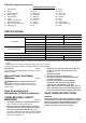
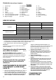
SPECIFICATIONS
• Due to our continuing program of research and development, the specifications herein are subject to change without
notice.
• Specifications and battery cartridge may differ from country to country.
• Weight, with battery cartridge, according to EPTA-Procedure 01/2003
Intended use
ENE034-1
The tool is intended for drilling and screw driving in wood,
metal and plastic.
General Power Tool Safety
Warnings GEA010-1
WARNING Read all safety warnings and all
instructions. Failure to follow the warnings and
instructions may result in electric shock, fire and/or
serious injury.
Save all warnings and
instructions for future reference.
CORDLESS DRILL SAFETY
WARNINGS
GEB051-2
1. Use auxiliary handle(s), if supplied with the tool.
Loss of control can cause personal injury.
2. Hold power tool by insulated gripping surfaces,
when performing an operation where the cutting
accessory may contact hidden wiring. Cutting
accessory contacting a “live” wire may make exposed
metal parts of the power tool “live” and could give the
operator an electric shock.
3. Always be sure you have a firm footing. Be sure
no one is below when using the tool in high
locations.
4. Hold the tool firmly.
5. Keep hands away from rotating parts.
6. Do not leave the tool running. Operate the tool
only when hand-held.
7. Do not touch the drill bit or the workpiece
immediately after operation; they may be
extremely hot and could burn your skin.
8. Some material contains chemicals which may be
toxic. Take caution to prevent dust inhalation and
skin contact. Follow material supplier safety data.
SAVE THESE INSTRUCTIONS.
WARNING:
DO NOT let comfort or familiarity with product (gained
from repeated use) replace strict adherence to safety
rules for the subject product. MISUSE or failure to
follow the safety rules stated in this instruction
manual may cause serious personal injury.
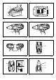
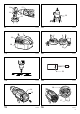
1. Red indicator
2. Button
3. Battery cartridge
4. Star marking
5. Switch trigger
6. Lamp
7. Reversing switch lever
8. Speed change lever
9. Action mode change lever
10. Adjusting ring
11. Graduations
12. Arrow
13. Steel band
14. Grip base
15. Side grip
16. Protrusion
17. Groove
18. Sleeve
19. Bit holder
20. Bit
21. Screw
22. Hook
23. Limit mark
24. Rear cover
25. Screws
26. Arm
27. Spring
28. Recesed part
29. Carbon brush cap
30. Hole
Model DDF441 DDF451
Capacities
Steel 13 mm 13 mm
Wood 50 mm 65 mm
Wood screw 6 mm x 75 mm 10 mm x 89 mm
Machine screw 6 mm
No load speed (min
-1
)
High (3) 0 – 1,700
Medium (2) 0 – 600
Low (1) 0 – 300
Overall length 238 mm
Net weight 2.3 kg 2.4 kg
Rated voltage D.C. 14.4 V D.C. 18 V