
Instructions

9 ENGLISH
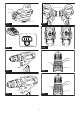
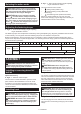
Selecting the action mode
CAUTION: Always set the ring correctly to
your desired mode mark. If you operate the tool
with the ring positioned halfway between the
mode marks, the tool may be damaged.
CAUTION: When you change the position
from " " to other modes, it may be a little dif-
this case, switch on and run the tool for a second
at the " " position, then stop the tool and slide
the ring to your desired position.
Fig.7: 1.2.
ring 3. Graduation 4.
This tool has three action modes.
•
Drilling mode (rotation only)
•
Hammer drilling mode (rotation with
hammering)
•
Screwdriving mode (rotation with clutch)
action mode changing ring and align the mark that you
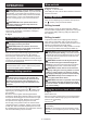
Adjusting the fastening torque
Fig.8: 1.2.
ring 3. Graduation 4.
Before actual operation, drive a trial screw into your material or a piece of duplicate material to determine which
the screw size and graduation.
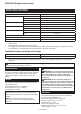
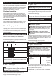
Graduation 1 2 3 4 5 6 7 8 9 10 11 12 13 14 15 16 17 18 19 20
Machine screw M4 M5 M6
Wood
screw
Soft wood
(e.g. pine)
– ø3.5 x 22 ø4.1 x 38
Hard wood
(e.g. lauan)
– ø3.5 x 22 –
– ø4.1 x 38
ASSEMBLY
CAUTION: Always be sure that the tool is
before carrying out any work on the tool.
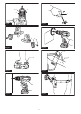
Installing or removing driver bit/
drill bit
Optional accessory
Fig.9: 1. Sleeve 2. Close 3. Open
Turn the sleeve counterclockwise to open the chuck
as it will go. Turn the sleeve clockwise to tighten the
counterclockwise.
Installing hook
WARNING: Use the hanging/mounting parts
for their intended purposes only, e.g., hanging the
tool on a tool belt between jobs or work intervals.
WARNING: Be careful not to overload the
hook as too much force or irregular overburden
may cause damages to the tool resulting in per-
sonal injury.
CAUTION: When installing the hook, always
If not, the hook
CAUTION: Make sure to hang the tool
securely before releasing your hold.
Fig.10: 1. Groove 2. Hook 3. Screw
The hook is convenient for temporarily hanging the tool.
the hook, insert it into a groove in the tool housing on
either side and then secure it with a screw. To remove,
loosen the screw and then take it out.
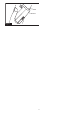
Using hole
WARNING: Never use the hanging hole for
unintended purpose, for instance, tethering the
tool at high location. Bearing stress in a heavily
loaded hole may cause damages to the hole, result-
Fig.11: 1. Hanging hole
hang the tool on a wall using a hanging cord or similar
strings.